3
Hearth & Home Technologies • LOGS-60 Installation Instructions • 2321-948 Rev. D • 10/15
13.
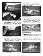
LOG #2 (SRV2300-704):
Install Log # 2. Place log so
that the larger end of the log is in contact with the locat-
ing screw and the small end of the log is resting on the
end of Log #1. See Figure 7.
14.
LOG #3 (2331-708):
Install Log # 3. Install log onto
shoulder screws #4 and #5 by lining up shoulder
screws with holes in bottom of log. See Figure 8.
16.
LOG #5 (SRV2331-704):
Install Log #5 onto shoulder
screws #8 and #9 by lining up the holes in the bottom
of the log with the shoulder screws as shown in Figure
10. Note that the properly placed log does not cover
any part of the burner. If burner is covered, log is in-
stalled backwards and burner rails can not be installed
properly. Turn log around to its proper position.
Figure 7. Log #2 (SRV2300-704)
1
1
22
33
11
22
Figure 8. Log #3 (SRV2331-708)
15.
LOG #4 (SRV2331-706):
Install Log # 4 onto shoulder
screw #6 by lining up shoulder screw with hole in bot-
tom of log. The other end of the log should rest on the
end of Log #3. See Figure 9.
Figure 10. Log #5 (SRV2331-704)
Figure 6. Log #1 (SRV2300-703) Left and Right Side Placement
1
1
11
Figure 9. Log #4 (SRV2331-706)
4
4
33
22
55
17.
LOG #6 (SRV2331-703):
Install Log # 6. Place log so
that the larger end without the fork is resting on the
fl
at
area on Log #5. The opposite end should be placed so
that it contact the edge of the media tray. When prop-
erly placed, this log is
fi
rm in its position. If it seems to
simply “balance” rather than rest, continue to adjust it.
Log #6 should not contact the inside back of the appli-
ance on a single-sided model, or the glass on a see
through model). See Figure 11.
6
6
Figure 11. Log #5 (SRV2331-704 and Log #6 (2331-703)
5
5
FLAT AREA
FLAT AREA
LOG CONTACTS EDGE
LOG CONTACTS EDGE


