10
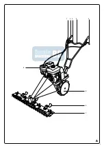
DESCRIPTION (FIG. A)
This machine is designed for mowing lawns in residential gardens. The machine is
not suitable for commercial use.
1. Throttle
2. Handle
3. Clutch lever forward
4. Handle
5. Reverse clutch lever
6. Wheel
7. Cutter bar
8. Enginer
9. Height guide
PACKAGE CONTENTS
• Scythe mower
• 2 wheels
• Cutter bar
• Long bolt with tappered locking nut
•
• Spark plug wrench
• Oil syringe
• Bolts and nuts
IMPORTANT
First install the machine and then fill the gearbox with 150 ml of gear oil. Use the
supplied oil syringe for this. Filling the gearbox with gear oil is necessary to prevent
the gears from wearing out within 5 minutes of use. Gear wear, caused by direct
use without topping up gear oil, is not covered by the warranty.
ASSEMBLING
The trencher is supplied partially assembled.
TOOLS NEEDED
• Spanner 17 mm
• Open-end wrench 14 mm
• Open-ended or socket wrench 10 mm
• Open-end or socket wrench 8 mm
• Socket wrench 14 mm
• Socket wrench 17 mm
• Socket wrench holder with ratchet
To simplify installation, follow the order below.
MOUNTING THE WHEELS IN FREEWHEEL POSITION
1. Slide a wheel tube onto the wheel axle as far as possible.
2. Insert a locking pin only through the wheel axle.
3. Press the lock onto the locking pin.
Assembly of the handle
Slide the handlebar support over the handlebar holder. Insert the supplied bolt
through the round holes and screw the tapered locking nut (with the narrow side
toward the handlebar) onto the bolt. Lock the handlebar by pushing the cam on the
tapered nut into the recess.
MOUNTING THE HEIGHT GUIDES
1. Place the height guide brackets on the cutter bar.
2. Place a lock washer and spring washer over the 4 bolts.
3. Screw on with 4 nuts. Use a spanner and a socket wrench to fix the cutter bar.
4. Insert a bolt from below through a bracket and a height guide and secure with
a nut, lock washer and spring washer.
MOUNTING THE CUTTER BAR
1. Check that the drive ring is placed on the eccentric shaft.
2. Insert 4 bolts from bottom to top through the cutter bar.
3. Place the machine with the drive ring in the guide over the 4 bolts on the
cutter bar.
4. Place a lock washer and spring washer over the 4 bolts.
5. Screw on the cutter bar with 4 nuts. Use a spanner and a socket wrench to fix
the cutter bar.
6. Apply a liberal amount of grease to the eccentric shaft and guide.
BEFORE FIRST USE
THE MOTOR (FIG. B)
A Air filter
B Muffler
C Spark plug
D Throttle
E Pull starter
F Motor switch
G Start cord
H Fuel tap
J Choke lever
K Fuel cap
L Petrol tank
M Dipstick
N Drain plug
These machines are supplied without fuel and oil. Fill, before use, fuel and
oil to the correct level. Operating the machine without or with too little oil
can cause serious engine damage that is not covered by the warranty.
FILLING UP WITH FUEL
Always use fuel that meets the following specifications: unleaded petrol, minimum
octane rating 86.
Never top up with fuel while the machine is running. Allow the machine to
cool for at least 15 minutes after filling up before adding fuel.
Do not smoke near the machine or near the fuel. Never add fuel in the
vicinity of sparks, flames or open flames.
• Remove the cover (K) from the filling opening.
• Carefully pour the fuel into the filling opening. Do not fill the tank beyond the top
of the fuel filter.
• Replace the lid on the filling opening.
FILLING WITH ENGINE OIL
Use 4-stroke engine oil. SAE 10W-30 is suitable for general use at all
temperatures. Other viscosity can be used when the average ambient temperature
is within it specified ranges.
• Remove the dipstick (M) from the filling point.
• Fill the crankcase with the specified amount of oil.
• Refit the dipstick.
USE
DRIVE
The gearbox is filled with oil at the factory.
ADJUSTING THE HANDLE HEIGHT
1. Loosen the tapping nut on the handlebar holder.
2. Adjust the height of the handlebar.
3. Retighten the bolt and push the cam back into the recess
ADJUSTING THE CUTTING HEIGHT
The cutting height can be adjusted with the height guides (9).
1. Loosen the nuts.
2. Slide the height guides to the desired height.
3. Retighten the nuts.
Always set both height guides to the same height.
ADJUSTING THE WHEELS IN THE DRIVING POSITION
1. Pull the locking pin out of the wheel axle.
2. Slide the wheel tube back so that the holes in the wheel tube match the holes
in the wheel axle.
3. Insert a locking pin through the wheel tube and the wheel axle.
4. Press the lock onto the locking pin.
STARTING THE ENGINE (FIG. A + B)
Always start the machine at the job site and allow it to warm up. With the
machine running, check that all controls are working properly before
using it.
Содержание 57091HBM
Страница 2: ...2 5 ENGLISH 9 FRAN AIS 13 DEUTSCH 17 ESPA OL 21 ITALIANO 25 31...
Страница 3: ...3 A 2 3 4 5 6 9 7 1 8...
Страница 4: ...4 B A D K L M N B E G H F C J...
Страница 5: ...5 NEDERLANDS a 5 5...
Страница 29: ...29 ITALIANO 30 10 15 1 2 3 4 4 1 4 2 4 3 4 4 4 5 4 6 5 5 1 5 2 5 3 5 4 5 5 6...
Страница 30: ...30...
Страница 32: ...HBM Machines B V Grote Esch 1010 2841 MJ Moordrecht The Netherlands www hbm machines com...


