


Troubleshooting Chart
39
Troubleshooting Chart
38
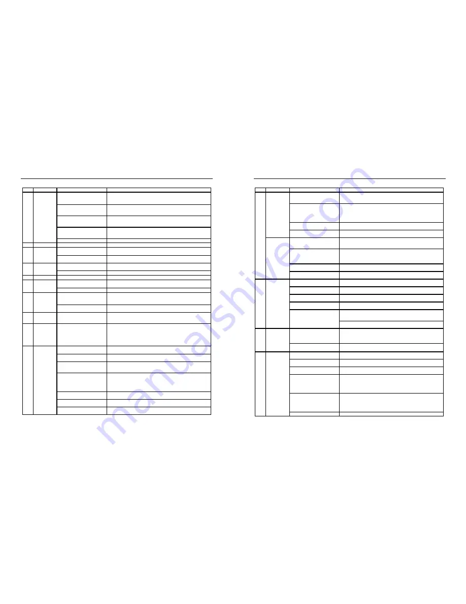
Code
Fault
Diagnosis Step
Remedy
1. Verify that FC4 Fuse on Fuse Board
is not open.
Remove FC from fuseholder. Measure continuity across fuse. If OK, reinstall fuse
and proceed to step 2. If Fuse is open, proceed to section titled "Open FC4 Fuse".
2. Verify high voltage output from Fuse
Board.
Disconnect plug from P6 connector of Fuse Board. Measure for 120VAC across pins
3 and 5 of P6 receptacle on Fuse Board. If OK, reconnect plug and proceed to step
3. If not OK, go to step 4.
3. Check for defective Harness.
Disconnect plug from E10 connector of Control Module. Measure for 120VAC across
pins 1 and 3 of Plug on Harness. IF OK replace Control Module. If not OK, replace
Harness.
4.Check for defective Transformer.
Disconnect plug from P4 connector of Fuse Board. Measure for 120VAC between
pins 4 & 6 of plug from transformer . If OK, proceed to step 5. IF not OK, replace
Transformer.
5. Fuse Board is defective
Replace Fuse Board.
EE
Bad Board
1. Defective Control Module
Replace Control Module.
1. Check for faulty wiring or connection. Inspect Display Interface Wiring. Ensure Display Interface Plug is securely attached
to Control Module. If OK, proceed to step 2.
2. Control Module and/or Display
Interface Assembly are defective.
Replace Control Module and/or Display Interface Assembly.
1. Check for faulty wiring or connection. Inspect Igniter wiring. Ensure Igniter Plug is securely attached to Control Module. If
OK, proceed to step 2.
2. Igniter is defective.
Replace Igniter.
SB
Keypad Failure
1. Keypad is defective.
Replace Display Interface Assembly.
1. Check for faulty wiring or connection. Inspect sensor wiring. Ensure sensor is plugged into back of control module. If OK,
proceed to step 2.
2. Sensor is defective.
Replace temperature sensor.
1. Pool water temperature exceeds
108°F.
Verify set point setting of remote thermostat is below 108°F. If set point setting of
remote thermostat is OK, or if heater is not configured for remote thermostat proceed
to step 2.
2. Verify that water flow is adequate
Verify that water flow to heater is above minimum required (25 GPM for H250IDL, &
40 GPM for H350IDL & H400IDL).
HF
Flame Present
with Gas Valve
Not Energized.
Gas Valve is defective.
Replace Gas Valve.
BO
Bypass operation. 1. Check to see if Control Module is in
Bypass Operation.
This is a normal display when heater is being controlled by a remote thermostat. No
service is required. If heater is not being controlled by remote thermostat, change
setting by using the MODE key to put the heater into STANDBY. Press and hold the
DOWN key and then press and hold the MODE key. HOLD down both keys for 3
seconds until the indication "bo" is removed from the display.
1. Verify that pump is running.
This is a normal display when the pump is off. Turn pump on. LO code should clear. If
LO does not clear, proceed to step 2.
2. Verify that water flow is adequate
Verify that water flow rate to heater is above minimum required (25 GPM for
H250IDL, and 40 GPM for H350IDL and H400IDL). If OK, proceed to step 3.
3. Check for faulty wiring or connection. Inspect water pressure switch wiring. Ensure wire harness terminals are securely
fastened to spade terminals on water pressure switch. If OK, proceed to step 4.
4. Verify state of water pressure switch
contacts.
Remove wire leads from water pressure switch and jumper leads. Operate heater.
Measure continuity across water pressure switch fault. If open, proceed to step 5. If
closed, LO code is not caused by vent pressure switch fault. Remove jumper from
wire leads and reconnect wire leads to water pressure switch.
5. Ensure that low pump pressure does
not exist.
Clean filter or clear blockages. Check position of valves in plumbing system. If OK
proceed to step 6.
5. Check for correct water pressure
switch setting.
Adjust water pressure switch setting per installation manual. If LO does not clear,
proceed to step 6.
6. Water pressure switch is defective.
Replace water pressure switch.
Water pressure
switch fault.
LO
SF
Temperature
sensor input
failure.
HS
Maximum return
water temperature
exceeded.
CE
Communication Error
Between Control
Module and Display
Interface Assembly
IO
Igniter Failure
BD
Bad Board or
Secondary High
Voltage Fault
IDL Heater Diagnostic Guide
IDL Heater Diagnostic Guide
Code
Fault
Diagnosis Step
Remedy
1. Check for faulty wiring or connection. Inspect vent pressure switch wiring. Ensure wire harness terminals are securely
fastened to spade terminals on vent pressure switch. If OK, proceed to step 2.
2. Verify state of vent pressure switch
contacts.
Remove wire leads from vent pressure switch and jumper leads. Operate heater.
Measure continuity across vent pressure switch. If closed, LO code is not caused by
vent pressure switch fault. If open, proceed to step 3. Remove jumper from wire leads
and reconnect wire leads to vent pressure switch.
3. Check for restricted for blocked flue.
Ensure that flue is not blocked or restricted. See indoor vent sizing requirements in
installation manual. If OK, proceed to step 4.
4. Vent pressure switch is defective.
Replace vent pressure switch.
1.Check for faulty wiring or connection. Inspect temperature limit switch wiring. Ensure wire harness terminals are securely
fastened to spade terminals on temperature limit switches. If OK, proceed to step 2.
2. Verify state of temperature limits’
contacts.
Remove wire leads from limit switch and jumper leads. Operate heater. Measure
continuity across limit switches. If closed, LO code is not caused by temperature limit
switch fault. If open, proceed to step 3. Remove jumper from leads and reconnect
leads to temperature limits.
3. Verify that water flow is adequate
Verify that water flow rate to heater is above minimum required (25 GPM for
H250IDL, and 40 GPM for H350IDL and H400IDL). If OK, proceed to step 4.
4. Temperature limit switch is defective. Replace temperature limit switch.
1. Ensure gas supply shutoff valves are
open.
Ensure that main gas shutoff installed adjacent to heater is open. Ensure that knob
on gas valve inside unit is in on position. If OK, proceed to step 2.
2. Check for low gas supply pressure.
Ensure inlet gas supply pressure exceeds minimum valve indicated on rating plate. If
OK, proceed to step 3.
3. Check for faulty flame sense wiring or
connection.
Inspect flame sense wiring. Ensure wire harness terminals are securely fastened to
flame sense and to control module. If OK, proceed to step 4.
4. Check for faulty gas valve wiring or
connection.
Inspect gas valve wiring. Ensure wire harness terminals are securely fastened to
spade terminals on gas valve. If OK, proceed to step 5.
1. Measure voltage across gas valve during trial for ignition. If 24 vac is present and
gas valve does not open, gas valve is defective. Replace gas valve.
2. If 24 vac is not present, gas valve relay on control module is defective. Replace
control module.
1. Check for defective blower on relay or
control module.
Disconnect Blower plug from Control Module. With heater off, measure continuity
across pins 1 and 2 and across 2 and 3 of receptacle on Control Module. If either pair
is closed, control module relay is defective. Replace control module. If OK, proceed
to step 2.
2. Vacuum switch is defective.
Replace blower vacuum switch.
1. Check for faulty vacuum switch
tubing.
Check tubing and replace if necessary. If OK, proceed to step 2.
2. Check for faulty vacuum switch wiring
or connection.
Inspect vacuum switch wring. Ensure wire harness terminals are securely fastened to
spade terminals on vacuum switch. If Ok, proceed to step 3.
3. Check for faulty blower wiring or
connection.
Inspect blower wiring. Ensure plug on blower is securely fastened to control module.
If OK, proceed to step 4.
4. Check for defective vacuum switch.
Disconnect Blower plug from Control Module. Measure resistance across Blower
windings. Winding resistance across lead should be in the following range: Black-to-
White: 10 to 14 ohms, Red-to-White: 18 to 22 ohms. If measured values vary
substantially from these values, Blower is defective. Replace. If OK, proceed to step
5.
5. Check for defective blower relay.
Disconnect blower plug from Control Module. Place heater in Pool or Spa mode.
Lower set point temperature to generate call for heat. During pre-purge period,
measure for 120VAC across pins 1 and 2. If 120VAC is not present, control module
relay is defective. Replace control module. If OK, proceed to step 6.
6. Vacuum switch is defective.
Replace blower vacuum switch.
Blower vacuum
switch closed.
Blower vacuum
switch open
5. Check for gas valve failure or gas
valve relay failure.
Vent pressure
switch fault.
Temperature limit
switch fault.
Ignition failure
IF
AC
AO
LO


