03/21
Model SP158.15
Page 4 of 8
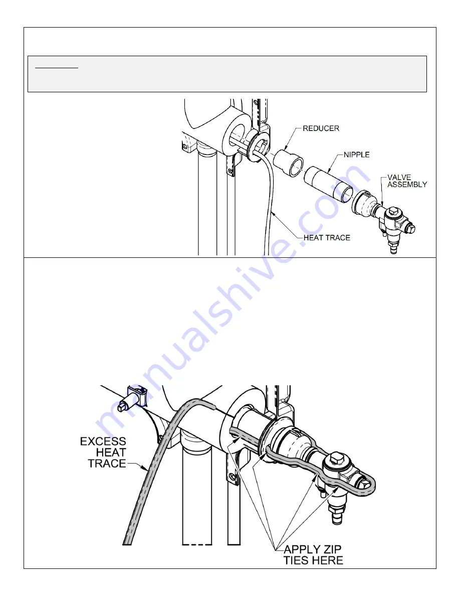
STEP 3: Plumbing
a) Run the heat trace out the grommet from Step 1, situating it within the nearest square cut in the grommet.
b) Connect and seal the galvanized
reducer, and then the galvanized
nipple, to the auxiliary outlet. The
nipple will run through the grommet,
with the heat trace alongside it.
c) Connect and seal the freeze valve
assembly to the end of the nipple.
Point the freeze valve drain fitting
downward.
d) Pressurize the plumbing and check
for leaks.
e) Make sure the heat trace is running
smooth and flat along the new
plumbing, but do NOT zip tie it into
place yet.
STEP 4: Heat Trace
a) Run the heat trace straight and level along the side of the plumbing and freeze valve. Wrap it around the
outlet plug of the freeze valve, then run it straight back along the opposite side.
b) Push the end of the heat trace through the open square cut in the grommet and feed the excess length
back within the jacket. The heat trace must run along the opposite side of the auxiliary outlet plumbing
until it rejoins the vertical shower piping. The excess length beyond this point should run out through the
insulation slit that the extra heat trace originally used. Store this excess length where the extra heat trace
was originally located.
c) Install the heat trace zip ties (found in a bundle of 6) approximately where shown. Use more than the 4
shown if needed.
The purpose of these zip ties is to ensure that the heat trace maintains solid
contact with the piping as continually as possible
– make sure the heat trace is ideally positioned
before tightening down the zip ties.
WARNING:
The heat trace must lay flush against the plumbing, contacting it wherever possible, in order
to transfer the necessary heat into the water. Failure to bring the heat trace into adequate contact with
the plumbing may cause local freezing within the plumbing, risking damage, leakage, and malfunction.


