background image


09/19   1200 Series Electric Water Coolers 


 Page 4 of 21   

C.  INSTALLATION OF HIGH-SIDE (LEFT) WATER COOLER 


23.  Remove the hanger bracket from the back of the cooler by removing (1) screw. 
24.  With the cooler laying on its back, remove the (4) screws holding the skirt to the bottom of the frame.  Then remove the 

skirt by sliding the skirt away from the cooler. 

25.  Mount the hanger bracket on the wall using (4) 

1/4” structural screws, in accordance with the installation drawing. 

a. 

NOTE:  The screws must engage into structural material such as concrete, metal backing, wood blocking, etc.  
DO NOT use drywall anchors. 

b. 

NOTE:  The hanger bracket has a notch indicating the centerline of the water cooler. 

26.  Using cutting pliers, cut the cable-tie holding the unconnected wires in the upper left side of the refrigerated cooler.  These 

wires will supply power, signal, and ground to the high side water cooler.  Take care not to damage the wires when cutting 
the tie. 

27.  Remove the protective plastic wrap from the feedthrough cover. 
28.  Feed the water tubing and wiring through the feedthrough cover.  Install the feedthrough cover by sliding its upper right 

tab behind the edge of the black cap of the right side water cooler (see installation drawing).  Use a bubble level to ensure 
the left edge of the feedthrough cover is vertical. Secure with a 

1/4” or #10 screw. 

a. 

NOTE:  Installing the screw into structural material is recommended.  Toggle bolts or drywall anchors can be 
used but they may make the unit more susceptible to damage from vandals. 

29.  Hang the cooler onto the hanger bracket.   

a. 

NOTE:  The bracket must go thro

ugh the holes in the cooler frame that are shaped like a sideways letter “P”. 

b. 

NOTE:  The bracket allows for some lateral adjustment of the cooler location.  Slide the cooler laterally until it 
touches the side of the feedthrough cover. 

30.  Secure both the lower right and lower left ends of the cooler to the wall using at least (2) 

1/4” or 3/8” structural screws.   

These screws should go through the holes which are approximately 5” from the bottom of the cooler. Washers may be 
required. 

a. 

NOTE:  The screws must engage into structural material such as concrete, metal backing, wood blocking, etc.  
DO NOT use drywall anchors. 

31.  Route the drain hose from the left unit to the right unit.  Attach to the open branch of the drain tailpiece using the supplied 

hose clamp, ensuring that the drain hose slopes downward over its entire length. 

32. 

Attach the 3/8” water supply line to the 3/8” connector in the left side unit. 

33.  Connect the wire connector in the left unit. 
34.  Remove the green ground screw from its hole in the left unit and use it to secure the green ground wire to that same 

location. 

35.  Snap wires into the plastic wire clip (near the ground screw) to keep them away from the sheet metal edges. 


D.  START-UP 


36.  Open the water supply valve and check the system for leaks. 
37.  Plug the power cord into the wall receptacle (which should presently be powered off at the breaker panel).  Check that all 

wiring is fully contained within the unit and that no wires are impeding fan blade movement. 

38.  Peel back the protective plastic from the bac

k flanges and top 1” of the skirt(s). 

39.  Taking care not to scratch the black plastic parts behind the bowl, reinstall the skirt(s).  Finish removing the protective 

plastic from the skirt(s). 

40.  Reconnect power at the breaker panel, then place a cup over the bubbler (to minimize splattering) and push the front 

button to activate the bubbler flow.  Keep the button depressed until all air is purged out of the water line. 

a. 

NOTE:  If the unit has a filter, run the bubbler for 10 minutes in order to properly flush the filter. 

41.  If a bottle filler has been installed, place a cup under the nozzle of the bottle filler and run the water until the air has been 

purged out of the water line. 

42.  If a high/low unit has been installed, place a cup over the bubbler of the second unit and push the front button to activate 

the bubbler flow.  Keep the button depressed until the air has been purged out of the water line. 

43.  The stainless steel panels can be cleaned with the provided cleaning wipe.   Buff off excess with a clean cloth or paper 

towel.  Do not allow the cleaning fluid to touch the plastic parts or the bottle filler. 

44.  After allowing a few minutes for the water to cool down, enjoy a cold drink of water. 


E.  OPTIONAL PROGRAMMING INSTRUCTIONS (BOTTLE FILLER UNITS ONLY) 


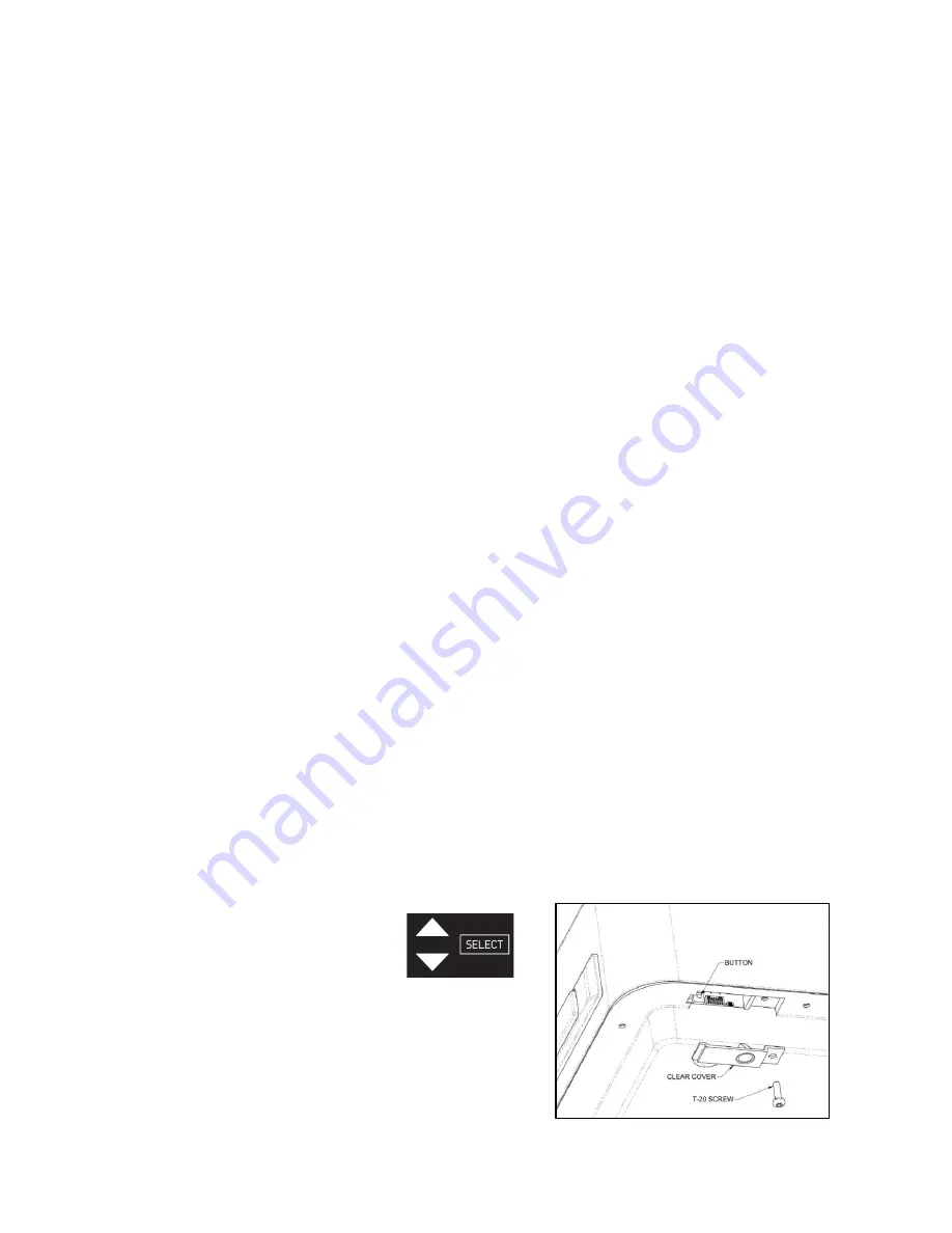
To enter programming mode, remove the clear cover underneath the bowl, and hold the button until the up/down arrow 
keys and 

“select” appear on the bottle filler display.  Programming mode enters at the top-level menu.  In general, the 

up/down arrows and select keys work as follows; 
 

Up/Down Arrows 

– Cycle through the top-level menu items or 

values in the programmable fields 
 
Select 

– enters programming of the associated top-level menu 

item, or sets value and advances to next programmable field, or 
programs value (indicated by value flashing) prior to returns to the 
main menu  
 
Programming the Haws 12 Electric Water Cooler through the bottle 
willer user interface is intuitive.  However, the following Electric 
Water Cooler and Bottle Filler Programming Table can be used as 
a guide while programming the unit, which are retained during 
power outages. 
 
Replace the clear plastic cover after programming the unit. 

Figure 3: Programming Mode Button 
viewed from underside of bowl


Содержание 1201S

Страница 1: ...l power to outlet before installing or servicing NOTICE A The electrical receptacle must have code approved ground fault circuit interrupter GFCI protection for personnel B Care should be taken not to damage refrigeration system lines or electrical wires during installation C Installation must conform to all applicable codes and standards NOTE TO INSTALLER Please leave this information with the Ma...

Страница 2: ...e for corrosive environments such as enclosed chlorinated pool areas or very dusty areas The ambient air temperature must be maintained between 40 F and 104 F at all times Installation into a location not meeting these limitations will void the warranty SUPPLY LINE The min recommended size is 1 2 IPS with 30 90 psig 2 6 ATM flowing pressure Where sediment or mineral content is a problem an upstrea...

Страница 3: ...ght Put a line on the nut using a marker Tighten exactly one additional full 360 degrees turn with a wrench using the line to count turns 9 Install the P trap If necessary trim the water cooler s drain tailpiece in place so it interfaces properly with the P trap inlet Pliers may be required to tighten the nuts to a leak tight condition 10 If the unit has a filter install the filter now Take care n...

Страница 4: ...ew from its hole in the left unit and use it to secure the green ground wire to that same location 35 Snap wires into the plastic wire clip near the ground screw to keep them away from the sheet metal edges D START UP 36 Open the water supply valve and check the system for leaks 37 Plug the power cord into the wall receptacle which should presently be powered off at the breaker panel Check that al...

Страница 5: ... returns to main menu Cancel returns to main menu without changing program Sets 12 hour clock AM or PM and advanced to programming OFF time see Note 1 Cancel returns to main menu with changing program Off 1 to 12 sets hour to turn Off energy saving and advance to A or P field see Note 1 Cancel returns to main menu without changing program Sets 12 hour clock AM or PM and advanced to OFF setting see...

Страница 6: ...er cord 6 Remove the black plastic cover underneath the bowl by removing the 4 screws using either a phillips bit or 5 16 nut driver 7 Remove the 3 T20 head screws attaching the bubbler to the bowl then pull up on the bubbler to release the push to connect fitting from it 8 Store the bubbler and T20 head screws in a safe location so that they can be reinstalled later 9 Install the cover plate by u...

Страница 7: ...steps 1 Remove the 4 screws holding the skirt to the bottom of the frame Then remove the skirt by sliding the skirt away from the cooler a NOTE For dual units the filter is in the right side unit 2 Place a towel or bucket below the cooler to collect the small amount of water that may drip from the filter head or filter during the next steps 3 Optional Turn the water supply valve to the off positio...

Страница 8: ...ATIONS I 1 WATER COOLER INDICATION LIGHTS ALL MODELS EXCEPT 1201S AND 1202S Power Red LED o Solid ON when power is applied Filter Blue LED Filtered units only o Solid ON Filter life 100 to 11 remaining o Intermittent Flash once 3 second Filter life 10 to 0 remaining o Rapid Flash once second Filter life expired Energy Saving Green LED o OFF Energy Saving Mode disabled o Solid ON Energy Saving Mode...

Страница 9: ...whether the solenoid valve is working 3 Low water flow from bubbler a b c d e Replace filter Verify minimum 30 psig supply pressure Verify supply valve is in full open position Unscrew nozzle and flush with clean water Replace nozzle 4 Low water flow from bottle filler a b c d e Replace filter Verify minimum 30 psig supply pressure Verify supply valve is in full open position Unscrew aerator and f...

Страница 10: ...e unit and ensure fan runs initially for approximately 10 seconds Clean condenser fins of dust and debris Verify inlet water and ambient temperatures are below specification maximum 2 E012 SENOB Bottle filler sensor is obstructed a b c Clear error in programming mode and power cycle unit and check error to validate Remove obstruction from aperture Clean aperture with soft cloth that won t scratch ...

Страница 11: ...ance Statement This device complies with Industry Canada licence exempt RSS standard s Operation is subject to the following two conditions 1 this device may not cause interference and 2 this device must accept any interference including interference that may cause undesired operation K 2 2 Declaration de Conformité Le présent appareil est conforme aux CNR d Industrie Canada applicables aux appare...

Страница 12: ...so includes costs of outbound freight but not express freight of the part or parts from the factory repair department but only if the part or parts and the purported defect or defects are covered by this LimitedWarranty in Haws sole discretion When the product is located outside the United States and Canada Haws obligation under this Limited Warranty includes only providing a replacement for any p...

Страница 13: ...C111 HC111 HC111 14 FAN MOTOR HC117 HC117 HC117 HC117 HC117 HC117 HC117 HC117 15 THERMOSTAT 5810 5810 5810 5810 5810 5810 5810 5810 16 COMPRESSOR THERMAL PROTECT HC115 HC115 HC115 HC115 HC115 HC115 HC115 HC115 17 COMPRESSOR START RELAY HC116 HC116 HC116 HC116 HC116 HC116 HC116 HC116 18 BOTTLE FILLER DRAIN BASIN 0410000286 0410000286 0410000286 0410000286 19 BOTTLE FILLER ASSEMBLY 1930 1930 1930 19...

Страница 14: ... WITHOUT NOTICE APPROVED DRAWN PART NUMBER SCALE REVISION JL 07 25 18 5 12XX ELECTRIC WATER COOLERS 1 8 TM 09 29 20 DRAWING TYPE SIZE A 5343 BY DHP PARTS BREAKDOWN DATE DATE REV ECN 5595 CHK D MODEL S 1455 KLEPPE LANE SPARKS NEVADA 89431 775 359 4712 FAX 775 359 7424 E MAIL HAWS HAWSCO COM WEBSITE WWW HAWSCO COM DHP ECN WHEN ORDERING PARTS PLEASE SPECIFY PART NUMBER SHEET 2 OF 2 0510000866 2020 Ha...

Страница 15: ...HIS DOCUMENT IS TRUE AND CORRECT AT TIME OF PUBLICATION CONTINUED PRODUCT IMPROVEMENTS MAKE SPECIFICATIONS AND MEASUREMENTS SUBJECT TO CHANGE WITHOUT NOTICE APPROVED DRAWN PART NUMBER SCALE REVISION JL 07 25 18 5 1 12 TM 09 29 20 DRAWING TYPE SIZE A 5343 BY DHP INSTALLATION DATE DATE REV ECN 5595 CHK D DHP WEBSITE WWW HAWSCO COM MODEL S 1455 KLEPPE LANE SPARKS NEVADA 89431 775 359 4712 FAX 775 359...

Страница 16: ...3 4 349mm 2020 Haws Corporation All Rights Reserved HAWS and other trademarks used in these materials are the exclusive property of Haws Corporation THIS DOCUMENT IS TRUE AND CORRECT AT TIME OF PUBLICATION CONTINUED PRODUCT IMPROVEMENTS MAKE SPECIFICATIONS AND MEASUREMENTS SUBJECT TO CHANGE WITHOUT NOTICE APPROVED DRAWN PART NUMBER SCALE REVISION JL 07 25 18 5 1 12 TM 09 29 20 DRAWING TYPE SIZE A ...

Страница 17: ...tion THIS DOCUMENT IS TRUE AND CORRECT AT TIME OF PUBLICATION CONTINUED PRODUCT IMPROVEMENTS MAKE SPECIFICATIONS AND MEASUREMENTS SUBJECT TO CHANGE WITHOUT NOTICE APPROVED DRAWN PART NUMBER SCALE REVISION JL 07 25 18 5 1 12 TM 09 29 20 DRAWING TYPE SIZE A 5343 BY DHP INSTALLATION DATE DATE REV ECN 5595 CHK D MODEL S 1455 KLEPPE LANE SPARKS NEVADA 89431 775 359 4712 FAX 775 359 7424 E MAIL HAWS HAW...

Страница 18: ...BING SUPPLIED HIGH EWC TUBING CONNECTION ON LOW COOLER ROUTE TUBING THROUGH CIRCULAR HOLE IN SHEET METAL 3 8 ELBOW FIELD CONNECTION 2020 Haws Corporation All Rights Reserved HAWS and other trademarks used in these materials are the exclusive property of Haws Corporation THIS DOCUMENT IS TRUE AND CORRECT AT TIME OF PUBLICATION CONTINUED PRODUCT IMPROVEMENTS MAKE SPECIFICATIONS AND MEASUREMENTS SUBJ...

Страница 19: ... CARE SHOULD BE TAKEN TO ENSURE THAT THE P TRAP CAN SEAL TO THE STUB OUT PROPERLY AND STILL ALIGN TO THE DRAIN TAILPIECE LOCATED AT THE GIVEN DIMENSIONS 3 4 5 6 HIGHEST LOWEST P TRAP HEIGHTS 5 LOW COOLER BRACKET HEIGHT ADULT STANDING ADULT ADA CHILD ADA 33 7 8 28 3 8 25 3 8 RETROFIT TABLE MANUFACTURER MODEL HAWS ALL MODELS STARTING WITH HWUACP ELKAY HALSEY TAYLOR ALL MODELS STARTING WITH EB EI EMA...

Страница 20: ...OFIT INSTALLATION DETAILS PAGE 20 OF 21 A WALL RECEPTACLE WITH A STANDARD SIZE WALL PLATE SHOULD BE LOCATED WITHIN THIS AREA HAWS COOLER MOUNTING BRACKET PERMISSIBLE ELECTRICAL RECEPTACLE LOCATIONS 1 26mm 6 1 4 159mm 3 77mm 10 5 8 271mm 14 356mm 13 1 8 334mm 6 152mm 4 1 8 105mm 5 7 8 149mm 5 127mm 2X 1 7 8 48mm HAWS COOLER MOUNTING BRACKET PERMISSIBLE WATER SUPPLY LOCATIONS WATER SUPPLY VALVE IS P...

Страница 21: ...RAWN PART NUMBER SCALE REVISION JL 07 25 18 5 1 8 TM 09 29 20 DRAWING TYPE SIZE A 5343 BY DHP INSTALLATION DATE DATE REV ECN 5595 CHK D MODEL S 1455 KLEPPE LANE SPARKS NEVADA 89431 775 359 4712 FAX 775 359 7424 E MAIL HAWS HAWSCO COM WEBSITE WWW HAWSCO COM DHP ECN SHEET 7 OF 7 0510000866 D 12XX ELECTRIC WATER COOLERS NOTE THE LEFT EDGE OF THE LABEL FACING OUT THE SIDE DURING INSERTION OF FILTER IN...

Отзывы: