


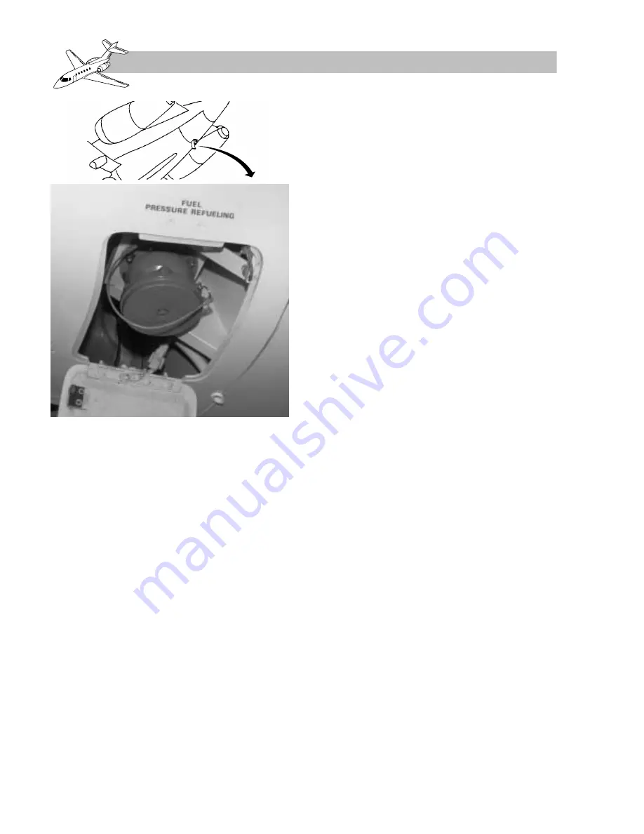
Fuel is loaded or off-loaded through a self-seal-
ing coupling, accessible through a hinged door
recessed into the ventral tank on the right side
of the airplane (Figure 5-7). A pressure-re-
ducing valve inside the coupling reduces re-
fueling pressure within the system. Restrictors
(within the low-pressure cocks) and surge re-
lief valves eliminate transient high pressure.
NOTE
Part of the fuel system pipelines are
common to both the fuel feed and
refuel/defuel systems. Because of
the location of the surge relief valves,
the low-pressure cocks must be open
when refueling any tanks or defuel-
ing the wing tanks.
Thermal-relief valves are installed in the re-
fueling lines to provide protection against
thermal expansion of the fuel (Figure 5-8).
A pressure switch in the line to the master re-
fuel valve closes the master refuel valve and
any open tank refuel valves if an overpres-
sure situation is detected. A valve-shut indi-
cation is given at the refuel control panel.
Fuel flow into or from the system is controlled
by an electrically operated master refuel valve.
Additionally, each wing tank and the ventral
tank has an electrically operated refuel valve.
Each tank refuel valve can be mechanically po-
sitioned in the event of electrical failure.
Magnetic indicators on the refueling control
panel show SHUT, crosshatch, or OPEN for
each of the valves in the system. As each tank
is filled, its high-level float switch causes
the related tank valve to close. The tank valve
indicator on the refuel control panel will
show SHUT, and the tank FULL indicator
will illuminate. The valve indicators show
crosshatch when electrical power is off.
Should a malfunction cause any tank to over-
flow into its surge tank, a float-operated switch
in the surge tank causes the master refuel valve
and any open tank refuel valves to close. The
appropriate OVERFLOW indicator on the re-
fuel control panel will illuminate.
All tanks may be pressure refueled simulta-
neously. Intermediate fuel loads are acceptable
for the wing tanks and can be obtained by se-
lecting the refuel switch off at the required
quantity level.
Refer to the appropriate airplane manual for
refueling and defueling procedures.
5-8
FOR TRAINING PURPOSES ONLY
HAWKER 800 XP
PILOT TRAINING MANUAL
FlightSafety
international
Figure 5-7. Pressure Refuel/Defuel
Coupling
Содержание 800 XP
Страница 4: ......
Страница 6: ......
Страница 10: ......
Страница 104: ......
Страница 124: ......
Страница 126: ......
Страница 156: ......
Страница 158: ......
Страница 160: ......
Страница 170: ......
Страница 172: ......
Страница 174: ......
Страница 184: ......
Страница 186: ......
Страница 198: ......
Страница 200: ......
Страница 202: ......
Страница 222: ......
Страница 264: ......
Страница 266: ......
Страница 268: ......
Страница 276: ......
Страница 278: ......
Страница 280: ......
Страница 290: ......
Страница 292: ......
Страница 310: ......
Страница 312: ......
Страница 314: ......
Страница 328: ......
Страница 338: ......
Страница 340: ......
Страница 342: ......
Страница 352: ......
Страница 354: ......
Страница 356: ......
Страница 378: ......
Страница 412: ......
Страница 414: ......
Страница 416: ......
Страница 474: ......
Страница 476: ......
Страница 478: ......
Страница 486: ......
Страница 500: ......
Страница 502: ......
Страница 504: ......


