Hateflex spiral hose
EN
14
Art. Nr.: 5090031096 Rev.: 02/2021-10-14
4
Distance (A)
5
Ø d
outside
Safety duct
6
Ground trench: stone-
less, with 10 cm compacted
sand bed
7
Height pipe bond
8
10 cm: limitation above the embedment according
to DIN EN 1610
9
Coverage
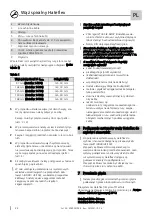
Based on the ducts outer diameter, consider the following
distances: (see Table 1).
Table 1
Hauff-spiral hose Ø d
outside
Distance (A)
87 mm (Hateflex 14078)
min. 30 mm
102 mm (Hateflex 14090)
min. 30 mm
125 mm (Hateflex 14110)
min. 40 mm
140 mm (Hateflex 14125)
min. 40 mm
168 mm (Hateflex 14150)
min. 40 mm
5
If more than two hoses are laid, the spacers must be
plugged together.
The eyelet must be placed on the spigot (see fig.: 3
and 4).
6
In the first layer, place the spacers directly on the
soil
and clip in the hose.
7
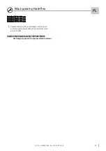
Backfilling of the space around and between the
pipes.
8
In the case of multi-
layer hose systems, the spacers
are placed on the respective hose layer below. The
hoses can now be clipped in place (see fig.: 2).
9
Go on with the follo
wing layers in a similar way.
To avoid a damage of the pipes and seal inserts
of the cable entry systems (HSI90 and HSI150),
use only slightly compacting machines for com-
pacting of the filling material
Please note the following rules therefore:
•
Technical guideline ZTVE-StB 94/97 (19) and
ZTVE-StB 97 (18)
•
DIN norms about classification of grounds
The usage of middle and heavy stamping or
vibrating machines in part of the summit
covering (measured in compacted status) is not
allowed under 1 m!
Following factors show the possible transfer
lengths:
•
Cable (type/ weight/ flexibility)
•
Cable run (height)
•
Quantity/ position/radius of curves/inaccuracy
•
Coefficient of friction (cable/pipe wall)
•
Lubricant (type/ quantity)
•
Method and speed of the move-in ( incl.
surface temperature)
•
Proportion pipe ID/cable OD
•
Quality of the installation, for example:
Pipe support/ compaction of the embedment
material = influence onto pipe deforming,
Backfilling/ compaction of the embedment
around pipe bows/ curves = important for ab-
sorption of mechanical load while cable entry.
6
Connection of the Hateflex hose system
onto chambers and stations
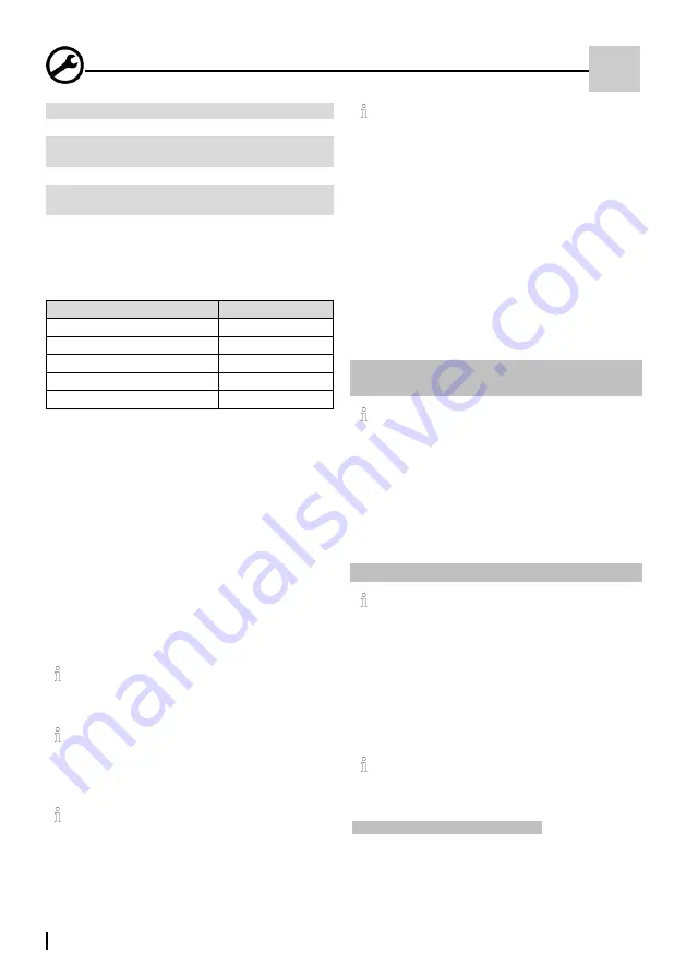
For the connection of the Hateflex hose systems
onto chambers and stations, you can use the
Hauff Cable Entry System (HSI90/HSI150). HSI
Cable Entry Systems need to placed in formwork
before concreting.
For the pipe connection system for all pipe di-
mensions of the Hatefles hose system, you can
use pipe connection sleeves made from rubber.
The cable entry system is not able to absorb
weight/ pressure of the cable safety duct.
7
Bending radiuses
The minimum bending radiuses of the duct ma-
nufacturers must be observed.
The following minimum radiuses apply to Hauff
-Technik
Hateflex systems at an
installation temperature of 20 °C:
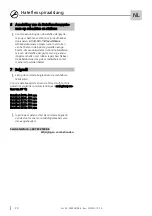
Hateflex14078: 400 mm
Hateflex14090: 400 mm
Hateflex14110: 500 mm
Hateflex14125: 600 mm
Hateflex14150: 900 mm
However, the minimum bending radiuses of the
media lines/cables to be installed must be obser-
ved.
Service tel 49 7322 1333-0
Subject to change!


