background image

7. 

CAUTION: 

The lathe bed is heavy. Have someone help lift it on the stand. 

8. 

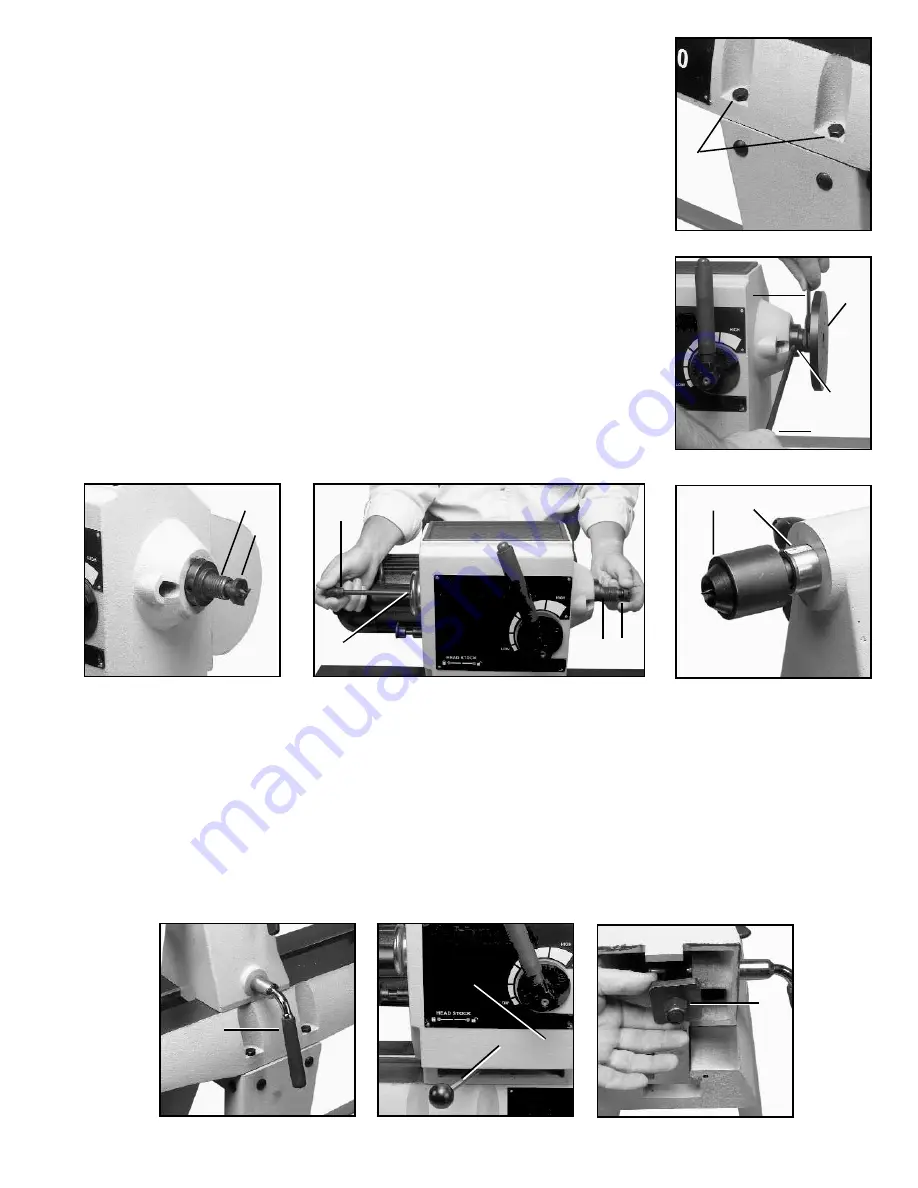
Position the lathe bed so that the holes in the lathe bed are directly above the 

holes in the stand. 
9. 

Secure the lathe bed to the stand using the eight M8 x 35mm Hex head  screws 

(A)  Fig. 9 through the lathe bed and through the stand. Attach a washer, lockwasher, 
and nut and tighten  securely. 
10.  Before tightening all hardware, press down on stand until legs adjust to floor 
surface. Securely tighten all  hardware. 
11.  Slide the tool rest and tailstock back into the lathe bed. 
12.  Have someone help lift the headstock on the lathe bed and slide it into position. 


HEADSTOCK SPUR CENTER


The 46-715 comes with a faceplate attached. Before inserting the spur center in the 
spindle, this faceplate must be removed. Insert the knockout bar (A) Fig. 10 in the side 
hole of the spindle (B) Fig. 10 to hold the spindle in place. Use the supplied wrench (C) 
Fig. 10 to loosen the faceplate. Remove the faceplate (D) by turning it counterclock- 
wise with your hand. The spur center (A) Fig.11 is equipped with a No. 2 Morse Taper 
shank. Insert this shank into the headstock spindle (B). 

NOTE: 

Before inserting the spur 

center (A), clean both the shank of the spur center and the inside of the headstock 
spindle to remove any grease or debris. To remove the tapered shank spur center (A) 
Fig. 11 from the headstock spindle (B) Fig. 11, use the knockout bar (C) Fig. 12 through 
the hole (D) in the opposite end of the spindle to push the spur center out.


IMPORTANT: NEVER DRIVE THE WORKPIECE INTO THE SPUR CENTER WHEN 
IT IS MOUNTED IN THE HEADSTOCK

.


See instructions on setting the spur center into the workpiece in the 

“OPERATION“


section of this manual under “

CENTERING THE WORK

.”


Fig. 9 


Fig. 10 


Fig. 11 

TAILSTOCK LIVE CENTER 

Fig. 12 

Fig. 13 

The tailstock live center (A) Fig. 13,  supplied with  your  lathe,  is equipped with a No. 2 Morse  Taper  shank. 

NOTE: 

Before 

inserting the live center, clean both the shank and the inside of the tailstock to remove any grease or debris. To remove the 
live center (A) from the tailstock spindle (B), use the knockout bar through the hole in the opposite end of the spindle (in the 
same manner as the headstock). 

ADJUSTING CLAMPS ON THE HEADSTOCK AND TAILSTOCK 

The headstock and tailstock can be moved along the lathe bed. A downward push on the tailstock handle (A) Fig. 14 locks 
the mechanism, while an upward movement of the handle releases the securing action. The headstock (A) Fig. 15 is loosened 
by  moving  the  handle  (B)  to  the  right.  The  clamps  are pre-set at  the  factory. However,  should  either  need  adjusting,  use  a 
15/16"  wrench to  slightly  loosen  or  tighten  the  nut  (A)  Fig.  16  shown  here on  the  tailstock. 

NOTE:  Clamp  headstock  and 

tailstock firmly before operating the lathe. 


Fig. 14 

Fig. 15 

6


Fig. 16 


B A 


A


Содержание JIB W0903X

Страница 1: ...14 Variable Speed Wood Lathe JIB W0903X INSTRUCTION MANUAL ...

Страница 2: ... parts Nonslip footwear is recommended Wear pro tective hair covering to contain long hair 12 SECUREWORK Useclampsoraviseto holdworkwhen practical It s safer than using your hand and frees both hands to operate tool 13 DON TOVERREACH Keep properfooting and balance at all times 14 MAINTAIN TOOLS IN TOP CONDITION Keep tools sharp and clean for best and safest performance Follow instructions for lubr...

Страница 3: ...interfere with the turning tool at the finished dimension of the workpiece 16 DO NOT WEAR GLOVES NECKTIE OR LOOSE CLOTHING when operating this tool 17 ROUGH CUT THE WORKPIECE as close as possible to the finished shape before installing it on the faceplate 18 TIGHTEN ALL CLAMP LOCKING HANDLES before operating 19 EXAMINE THE WORKPIECE FOR FLAWS and test glue joints before placing the workpiece in to...

Страница 4: ...ood quality paste wax WARNING FOR YOUR OWN SAFETY DO NOT CONNECT THE TOOL TO THE POWER SOURCE UNTIL THE TOOL IS COMPLETELY ASSEMBLED AND YOU READ AND UNDERSTAND THE ENTIRE OWNER SMANUAL CARTON CONTENTS Fig 1 1 Headstock Assembly 2 Tool Rest Assembly 1 Knockout Bar 2 Spindle Wrench 3 Live Center 4 Drive Center Fig 2 3 Tailstock Assembly 4 Lathe Bed 5 Leg 4 6 Short Tie Bar 2 7 Stand Top 8 Long Tie B...

Страница 5: ...ough the stand top Secure with flat washers lockwashers and hex nuts Fig 3 Fig 4 Fig 5 Fig 6 Fig 7 Fig 8 ATTACHING LATHE BED TO STAND The 46 715 lathe comes attached to plyboard To attach the lathe bed to the stand 1 Remove the security bars A Fig 4 that are attached to both ends of the lathe bed by removing the two screws B Fig 4 that secure it 2 CAUTION The headstock is very heavy Have someone h...

Страница 6: ...e the tapered shank spur center A Fig 11 from the headstock spindle B Fig 11 use the knockout bar C Fig 12 through the hole D in the opposite end of the spindle to push the spur center out IMPORTANT NEVER DRIVE THE WORKPIECE INTO THE SPUR CENTER WHEN IT IS MOUNTED IN THE HEADSTOCK See instructions on setting the spur center into the workpiece in the OPERATION section of this manual under CENTERING...

Страница 7: ...ork on the faceplate Fig 18 NOTE CLAMP TOOL REST FIRMLY BEFORE OPERATING THE LATHE ADJUSTING CLAMP ON TOOL REST To adjust the tool rest clamping action use a 15 16 wrench to adjust the nut A Fig 16 in the same manner as the headstock and tailstock Fig 17 ATTACHING ON OFF SWITCH TO TOOL Fig 18 The ON OFF Switch comes unattached to the tool to protect it from damage in shipping Toattach the ON OFF S...

Страница 8: ...RUNNING This tool provides variable rate spindle speeds from 450 to 2600 RPM To change speeds depress the release A Fig 23 and rotate the lever B Turning the lever clockwise increases the speed while turning it counterclockwise decreas es the speed Fig 23 ALIGNING HEADSTOCK CENTER TO TAILSTOCK CENTER The tailstock will move slightly when it is tightened To ensure that the tailstock center will alw...

Страница 9: ...raper E is mainly used for the outside of bowls Fig 26 HOW TO TURN SPINDLES Working with any material that is attached to the lathe centers is called spindle turning the principal type of wood turning for chair and table legs lamp stems etc The turning of spindles can be done with either a scraping or cutting technique The cutting technique by virtue of faster wood removal and a cleaner surface is...

Страница 10: ...com pletion an index mark should be made as a guide for re centering Fig 31 A permanent indexer can be made by grinding off one corner of one of the spurs MOUNTING THE WORK Mount the work by moving the tailstock to a position about 1 or 1 1 2 from the end of the workpiece and locking it in this position Advance the tailstock center by turning the feed handle until the center cup makes contact with...

Страница 11: ... the same direction it is advancing 3 The tool is held well up on the work with the bevel or grind tangent to the revolving surface Fig 35 This position will give a clean shearing cut When pushed straight into the work Fig 35 the gouge has a scraping action normally a poor practice in spindle turning The roughing cut is continued until the work approaches 1 8 of the required diameter Once a cylind...

Страница 12: ...nd holds the calipers in the cutting groove When parting tool cuts are deep a clearance cut should be made alongside the first cut Fig 40 to prevent burning the tool point SQUARING AN END The parting tool can be used to quickly square an end Since the parting tool is a rough cutter the cut can be smoothed by the use the skew However the whole operation can be done with the skew In using the skew m...

Страница 13: ...r makes this impossible use the skew in a flat scraping position If the cutting tech nique is used engage only with the heel of skew in a very light cut Fig 43 Fig 45 Fig 44 Fig 45 CUTTING SMALL BEADS Beads can be scraped or cut Using the spear chisel is the easiest method of scraping and works best on beads separated by parting tool cuts Fig 46 Scraping is slower than cutting and is not as clean ...

Страница 14: ...ng edge is the contact point with the wood As the cut progresses toward and around the end of the curve the handle is gradually raised and swiveled to the right Fig 53 in order to maintain the tangency between the grind and the surface being cut Figs 54 and 55 show the cutting of a long taper with a skew The operation differs from smoothing a cylinder only at the start of the cut The starting cut ...

Страница 15: ...58 it will be well up on the work and tangent with the cut surface Make only one half of the cut at a time then reverse the chisel to cut the other half The occasional turner should make cove cuts with a scraping technique using either the small gouge or round nose chisel SQUARE SECTIONS When the turning has a square section joint the stock before turning Good centering is essential since any erro...

Страница 16: ...cking block Fig 63 When screws are not permissible at all glue the work to the backing block by fitting a sheet of paper at the joint to allow later separation without damaging the wood Some work can be screwed or nailed from the face side into backing block Mount work less than 3 in diameter on the single screw center Fig 64 Fig 63 Fig 64 INBOARD OUTBOARD TURNING For workpieces that require addit...

Страница 17: ...rest to the desired height then retighten 7 Fig 68 illustrates a typical inboard faceplate turning set up Inboard faceplate turning is used mostly when the workpiece A will rotate freely over the lathe bed The workpiece A is mounted to a faceplate and the faceplate is threaded onto the spindle Note that the standard equipment tool rest B can be adjusted to turn the outside diameter of the workpiec...

Страница 18: ...ide the spindle handle out Pull the spindle lock to the out position see Fig 24A Fig 72 3 Remove the belt A Fig 73 from the pulley B NOTE When pulling the belt out or replacing the belt pull the spindle lock handle B Fig 72 out to its fullest position to give more room C Fig 73 for belt removal or replacement Replace new belt by using these instructions in reverse order Fig 73 19 8 A A A A B A C B...

Страница 19: ...14 WOOD LATHE 19 ...

Страница 20: ...01733 RETAINING RING 120 901771 HANDLE 36 901723 RUBBER PAD 121 n 912044 HANDLE T2 37 901742 HEADSTOCK 901772 HANDLE T1 38 901743 GEAR SHAFT 122 1342125 HEX SOC HD SCREW T1 39 901744 RETAINING RING 123 1246053 HEX SOC HD SCREW 40 901745 SPEED INDICATOR PLATE 124 1344933 HEX SOC HD SCREW 41 1344950 FLAT HD SCREW 125 n 912043 PLATE T2 42 1246110 PIN 903750 PLATE T1 43 901752 VARIABLE SPEED HANDLE 12...

Страница 21: ...093 SCREW HEX HD 172 901813 BED MOUNTING PLATE 174 1243526 FLAT WASHER 175 1246157 LOCK WASHER 176 1243398 HEX NUT 177 1349177 CARRIAGE HD SCREW 179 901812 LEG 180 901814 SHORT BRACKET 181 901816 LONG BRACKET 182 903746 LEG 183 903745 STAND HARDWARE PACK 21 ...

Отзывы: