

Werkzeug-Einstellungen ·
Tool settings
Tool settings
·
Réglages des outils
Werkzeug /
Tool /
Outil
Locator /
Locator
/
Positionneur
Kontakte /
Contacts /
Contacts
09 99 000 0501
09 99 000 0525
21 01 100 9021
21 01 100 9023
Kontakt /
Contact /
Contact
Artikelnum-
mer /
Part
number /
Référence
AWG
Werkzeugeinstellung /
Tool settings
/
Réglage de l’outil
Har
-speed,
Buchse/
female
/
femelle
21 01 100 9021
23
5
24
5
26
4
Har
-speed
M12, Buchse
/
female
/
femelle
21 01 100 9023
24
5
26
4
28
3
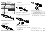
Abbildung ·
Figure
·
Figure
5 :
Schirmhülse aufschieben
/ Pushing the
shielding sleeve /
Glisser le manchon de blindage
9. Schieben Sie die Schirmhülse über den Isolierkörper bis an den An-
schlag des Schirmelements (Abb. 5).
9. Slide the shielding sleeve over the insulation body, all the way
up to the shielding element (Fig. 5).
9. Glissez le manchon de blindage sur le corps isolant jusqu’à la butée de
l’élément de blindage (Fig. 5).
Abbildung
·
Figure
·
Figure
6 :
Kupferfolie über Schirmung /
Copper foil
on shielding braid
/
Feuille de cuivre sur la tresse de blindage
Abbildung ·
Figure
·
Figure
9
:
Kodierung /
Coding /
Codage
12. Schieben Sie den Kabeladapter auf das Gehäuse, bis er einrastet. Be-
festigen Sie die Kabelverschraubung mit einem Schraubenschlüssel
SW 18 und verwenden Sie dabei ein Anzugsdrehmoment von 1,5 bis
1,8 Nm (Abb. 9).
12. Slide the cable adapter onto the hood/housing until it clicks
into place. Fasten the cable gland with a spanner A/F 18,
applying a tightening torque of 1.5 to 1.8 Nm (Fig. 9).
12. Faites glisser l’adaptateur de câble sur le boîtier jusqu’à ce qu’il s’en-
clenche en place. Fixez le presse-étoupe avec une ouverture de clé de
18 mm et un couple de serrage de 1,5 à 1,8 Nm (Fig. 9).
Montageanleitung, Art.-Nr. 09 10 008 3101 / 99.00 2020-12-08
Irrtum und technische Änderungen vorbehalten.
Assembly instructions, part no. 09 10 008 3101 / 99.00 2020-12-08
Errors and technical changes excepted.
Schéma d’assemblage, référence 09 10 008 3101 / 99.00 2020-12-08
Sauf erreur et changements techniques.
10. Für eine optimale Schirmübertragung empfehlen wir die Verwendung
eines Kupferbandes (Abb. 6).
10. For optimum shielding transmission, we recommend the use of
a copper tape (Fig. 6).
10. Nous recommandons l’utilisation d’une feuille de cuivre pour une trans-
mission optimale du blindage (Fig. 6).
Abbildung ·
Figure
·
Figure
7 :
Schirmgeflecht fixieren /
Fixing the shielding braid
/
Fixer la tresse de blindage
10. Fixieren Sie das Schirmgeflecht mithilfe eines Kabelbinders (Abb. 7).
10. Fix the shielding braid by using a cable tie (Fig. 7).
10. Fixez la tresse de blindage à l’aide d’un attache de câble (Fig. 7).
Abbildung ·
Figure
·
Figure
8 :
Montage Baugruppe /
assembly
of components
/
Assembler les composants
11. Schieben Sie die Baugruppe in das Gehäuse (Abb. 8), achten Sie da-
bei auf die Kodierung.
11.
Push the preassembled unit into the housing, thereby
observing the coding (Fig. 8).
11. Insérez le module pre-assemblé dans le boîtier, en observant le co-
dage (Fig. 8).


