MM-014763-001, Rev. E
32
2.
Route the cable from the antenna base to the location of where the mobile radio will be installed.
Remove headliner panel, interior panels, etc., as necessary. The cable must be kept out of casual
contact from persons within the vehicle. Tie and stow the cable as necessary to protect it from
possible chafing.
3.
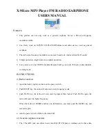
Using an appropriate crimp tool, crimp the supplied TNC RF connector to the end of the antenna
cable. For crimping instructions, see Figure 6-2 or the instructions supplied with antenna.
Actual Size; Dimensions are in Inches
(VS-AN-025167-010 Rev. A)
Figure 6-2: Crimping Instructions for TNC RF Connector
4.
The antenna cable is connected to the radio’s TNC receptacle-type (female) RF connector per a
procedure presented later in this manual. The cable and its TNC connector must be protected from
damage, dirt, and/or metal shavings which may be generated during the mechanical and electrical
installation of the radio. Temporarily tying the connector and cable-end within a small plastic bag is
recommended.
6.2.2
Install the GPS Antenna
(Required Only if Radio has GPS Receiver Option)
If the M7300 radio is equipped with the GPS receiver option, the GPS receiver requires connection to an
externally-mounted GPS antenna. The GPS antenna must be kept at least six (6) inches away from any
other antenna mounted on the vehicle and it must have at least six inches of surface ground plane beneath
it. The following antenna installation procedure is recommended:
Содержание M7300 Series
Страница 52: ...MM 014763 001 Rev E 52 RED RED RED WHITE RED Figure 8 4 Wiring Diagram for a Remote Mount Radio Installation ...
Страница 53: ...MM 014763 001 Rev E 53 Figure 8 4 Wiring Diagram for a Remote Mount Radio Installation Cont ...
Страница 80: ...MM 014763 001 Rev E 80 This Page Intentionally Blank ...