APEX
™
Exciter Incorporating FLO
™
Technology
Navigating the LCD Display Screens
Details of the Exciter Status Screens
Page: 3-24
888-2604-001
03/08/07
WARNING: Disconnect primary power prior to servicing.
These samples normally cycle through in two to four second steps. The sequence is
HPF, Amplifier, and HPF.
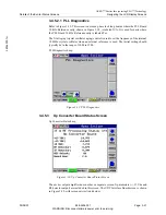
• Board Rev: This is the board revision for the Down Converter board.
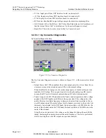
3.4.5.4.1 Down Converter Diagnostics
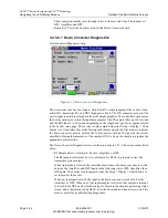
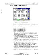
DownConverterDiagnostics.bmp
Figure 3-23 Down Converter Diagnostics
The down converter has four inputs, which are RF output samples of the exciter, trans-
mitter IPA, transmitter PA, and HPF (high power filter). The IPA sample is not used. The
exciter input is an internal loopback from the output amplifier. The controller board causes
the down converter to switch through these samples. The PA sample takes up to 5 seconds
and the HPF takes 5 to 90 seconds depending on the length and type of waveguide entered
in the exciter setup page. The exciter is only sampled when the Setup > Display > Chart
Source is set to monitor the exciter. During each sample period, the first action is to adjust
the down converter gain to provide the A/D converter with an IF signal of the correct
amplitude. During the remainder of the sample, RTAC acts on the sample to produce the
appropriate precorrection.
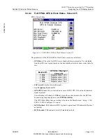
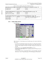
The Down Converter Diagnostics screen is shown in Figure 3-23, with screen entries listed
below.
• RF Sample Select: (Automatic, Exciter, Amplifier, or HPF.
The RF sample select must be set to automatic for RTAC to properly correct the
transmitter system output.
When Automatic is selected, the controller board causes the down converter to switch
between the Amplifier, and HPF inputs in the following order. HPF, Amplifier, then
HPF again. The exciter is only sampled when the Setup > Display > Chart Source is
set to monitor the exciter.
When not in automatic mode, the input to the down converter is locked to Exciter,
Amplifier, or HPF. When one of the input samples is selected, that sample is internal-
ly routed to the HPF, and PA feedback inputs, shown in the adaptive processing status
screen, and is therefore used by RTAC to set the linear and non-linear correction. This
mode is useful for troubleshooting diagnostics.

