


HS-3100/3200 Programming Manual
31
•
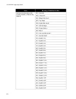
Code Bells:
Checking this option causes
only selected coded bells
to sound coded
signals. If coded bells are used the following options are then also shown:
-- No Restore:
If checked, the panel does not sound the Code again when the input
restores. If not checked, the panel sounds a single round of the Code when the input
restores
-- Code:
This is the sequence that is sounded when an alarm is received on this input. It
can be up to 4 digits long. Hexadecimal digits are used, thus each digit can be from 1 to
F, where A=10, B=11, C=12, D=13, E=14 and F=15.
-- Round:
This is the number of times the Code is repeated. It can be between 1 and 4
times for no restore inputs, and between 2 and 4 for restore inputs. Note: A minimum of
three rounds of code is required per NFPA 72.
•
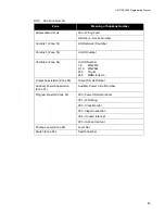
Night Sens. and Day Sens.:
Selects the Alarm threshold sensitivity for addressable
smoke sensors. Heat sensors always use Normal sensitivity. Increased sensitivity causes
alarms at lower levels of smoke. Sensors not attached to a switch always use the Night
Sensitivity. Sensors attached to a switch use Night Sensitivity while the switch is Off and
Day Sensitivity while the switch is On. Night Sensitivity must always be equal to or more
sensitive than the Day Sensitivity.
•
Manual Restart:
Check this to require that the control module not be reset by
System
Reset
but by
Manual Restart
. Use of this option requires that there be a
Manual Restart
function key assigned to the panel.
•
Trigger Manual Restart:
Check this option to have a monitor module generate a Manual
Restart when activated. Module Restart must have Non-reporting function.
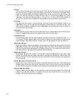
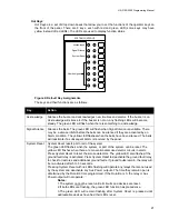
Pushbuttons
The push buttons located on the right hand side are:
•
Exit:
Closes the window and returns to the previous window.
•
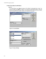
Devices:
Opens the Devices Window for the current circuit (Circuits Window only).
•
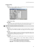
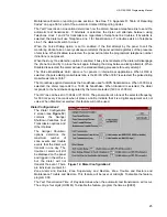
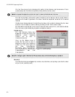
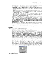
Copy:
Copies the circuit/device information, relates and message from another input to
the current input (see Figure 21). The current input does not have to be defined. Relates
cannot be copied between conventional and addressable input points. The
Panel ID,
Circuit ID
and
Device ID
(not always shown) list the circuit/device to be copied from.
Marking
Transfer Main Definition
copies the listed circuit/device type and function to the
current circuit/device.
Note:
Not all inputs can be copied to all other possible inputs.
Marking
Transfer Relates
copies the relates from the listed circuit/device relates to the
current one. This may cause some invalid relates. Marking
Transfer Message
causes the
message to be copied. Marking
Transfer Devices
(if shown) copies any device definitions
that the listed circuit contains. These devices copy messages and relates as based on
those settings above. There is no checking made at this time as to the validity of the
values copied.
Unexpected results can occur if care is not taken.
For each database
that is created, a warning about using copy is shown. Marking the check box in the
warning stops the box from appearing again for the database. This option can help speed
up the creation of a database. By completely defining one input, these values can be
copied to all other inputs, making any minor changes that are required after the copy.
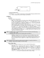
Figure 18: Copy Window
Содержание HS-3100
Страница 2: ......
Страница 4: ......
Страница 6: ......
Страница 64: ...Harrington Signal Inc 2519 4th Avenue Moline IL 61265 HARRINGTON FIRE ALARM SIGNAL INC...


