background image

HK4400

Operation

Before Operation

Safety Checklist

     □ 

Read and understand the Operator’s 

 Manual.

     □ 

Ensure the machine is equipped with 


safety stops for the hopper lift cylin-


ders and hopper door. Ensure that all 


shields and guards are in place. 

     □ 

Check the seat belt to make sure that 


it functions properly. 

     □ 

Know the location and function of all 


controls and how to stop quickly in an 


emergency. The machine controls are 


identified in the previous Controls 


Identification section. 

     □ 

Replace damaged or missing safety

 decals. 

Perform the Daily Maintenance Checklist. 

     □ 

Check engine oil level

     □ 

Check hydraulic oil level

     □ 

Check fuel level

     □ 

Check engine coolant level

     □ 

Visually inspect machine for fluid 


leaks, loose hardware, damaged parts, 

 etc.

     □ 

Check radiator/oil cooler and screen 


for debris. 

     □ 

Check engine air cleaner intake

     □ 

Grease as needed – see maintenance 


section for grease locations and 

 intervals

     □ 

Visually inspect tires to ensure proper 


inflation

Setting the Sweeping Height

• 

Park on level ground.  

• 

Start the machine and raise the deck 


using the LH lever located on the 

 console. 

• 

Secure the deck using the deck lift 


safety locks. 

• 

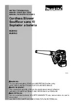
Adjust gauge wheel to desired height. 


The deck height is set from the factory 


in the middle hole of both the tube 


and the rod. At this setting, a new 


brush will contact the surface. To 


adjust the brush to be more aggres-


sive, raise the gauge wheel to the next 


set of holes that line up. To be less 


aggressive, lower the gauge wheel to 


the next set of holes that line up. The 


adjustments are approximately ¼” 


(.64 cm) increments. Set the gauge 


wheel  height the same on both sides. 

• 

Check the sweeping height. Repeat 


the steps in this section until desired 


sweeping height is determined. 

Adjusting the Anti-Scalp Rollers

• 

The anti-scalp rollers are set from 


the factory so that the surface of the 


roller is approximately 1” (2.5 cm) 


below the front edge of the deck. To 


adjust, remove the bolts and nuts 


identified below and adjust up or down 


accordingly. The rollers can be 


adjusted in 3/8” (.95 cm) increments. 


These are intended as anti-scalp 


rollers only and not intended to roll on 


the ground continuously.

14

Содержание 301012

Страница 1: ...HK4400 HK 4400 7 2020 OPERATOR S MANUAL SWEEPER Serial Number 20A01 Part 301012...

Страница 2: ...HK4400...

Страница 3: ...your dealer or Harper Industries Inc for clarification SAFETY WARNING ALL SHIELDS AND GUARDS MUST BE IN PLACE FOR PROPER AND SAFE OPERATION OF THIS EQUIPMENT WHERE THEY ARE SHOWN REMOVED IN THIS MANUA...

Страница 4: ...ng but not limited to consequential labor costs or transportation charges in connection with replacement or repair of defective parts This warranty does not apply to parts subjected to misuse abuse al...

Страница 5: ...ns Safety Locks Operation Before Operation Operation Operating Machine Sweeping Performance After Operation Storage Maintenance Hydraulic System Grease Zerk Locations Air Cleaner Cooling System Engine...

Страница 6: ...ed parking brake on all wheels Main Frame Welded and formed steel frame Tire and Wheels Front 24x9 5 12 Litefoot 4ply Rear 24x12 12 Litefoot 4ply Compaction Front 10 psi 69 kPa Rear 9 psi 62kPa Steeri...

Страница 7: ...ng the hopper as the top can reach approx 134 in 340 cm Deck Transition stationary shielding that surrounds the deck and provides a seal be tween the hopper and deck Sweeper Deck contains rotating swe...

Страница 8: ...may not be needed if the engine is already warm Transport Speed HI LO ALWAYS SWEEP WITH TRANSMISSION IN LOW Use high range when traveling between operations Park Brake ON OFF set park brake when unit...

Страница 9: ...indicator Once the in dicator turns off the machine is ready to start 4 Neutral Indicator illuminates when the machine is in neutral 5 Park Brake Indicator illuminates when the park brake is applied...

Страница 10: ...eck See instructions in the safety lock section Hopper Identification 1 Hopper Lift Cylinders used to raise and lower the hopper 2 Hopper Lift Safety Locks used to se cure the hopper in UP position Sa...

Страница 11: ...are removed re place them immediately Decal locations and part numbers are identi fied in the parts manual and can be obtained from your local Harper Dealer If you replace parts that have such decals...

Страница 12: ...m before repairing adjusting or disconnecting Wear proper hand and eye protection when searching for leaks Use wood or cardboard instead of hands when looking for leaks Keep all components in good rep...

Страница 13: ...ctor is running 9 Read manual before starting operating machine 10 Safety alert symbol 11 Do not use hook for lifting machine 12 Secure lifting cylinder with locking device before getting into hazardo...

Страница 14: ...hem make sure the decals are replaced with current versions and are on the replacement parts before the machine is operated again Safety Symbol Locations 12 5 6 7 10 REAR VIEW 8 10 5 10 13 1 1 2 3 10...
Страница 15: ...n the down position as shown in the picture below Hopper Lift Cylinders Safety Lock Secure the hopper in the UP position when working or standing below the hopper Install cylinder safety lock to the h...

Страница 16: ...ng Height Park on level ground Start the machine and raise the deck using the LH lever located on the console Secure the deck using the deck lift safety locks Adjust gauge wheel to desired height The...
Страница 17: ...during operation Starting the Machine Use the preheat position of the ignition switch until the glow plug indicator on the machine display turns OFF Preheating is not necessary if the engine is alread...
Страница 18: ...e the lift cylinder located on the rear side of the deck The deck lift cylinder is attached to a pivot link that allows the deck to float with the contour of the ground When the deck is lowered hold t...

Страница 19: ...ay to ensure proper temperature and fluid levels Tipping Angle Never operate the machine on an incline greater than 20 Never raise the hopper on an incline greater than 10 Accessing Paddle If the padd...

Страница 20: ...110 F and it con tains a kinematic viscosity rating around 46 cSt at 40 C 1cSt 1mm s Mobil DTE 25 Mobil DTE 15M Amoco Rykon Premium Oil ISO 46 Chevron Rykon Premium Oil ISO 46 Conoco Hydroclear AW MV...

Страница 21: ...above To access steering cylinder pivot the seat for ward by releasing the spring pins located at the rear of the seat as shown in the pictures below 19 Air Intake Air Filter HOPPER LIFT LINKAGE PINS...

Страница 22: ...adiator level daily and only when engine is cool and not running Remove cap radiator fill slowly to relieve any pressure that may be built up Fill up radiator with coolant 50 wa ter 50 antifreeze unti...

Страница 23: ...e located below the fuel tank These components can be accessed through the frame cutouts between the two rear tires 21 Fuel Filter Fuse Relay Panel Located under operators console through the access d...

Страница 24: ...the paddle rotor for damaged seals or excessive movement of the shaft contained by the bearing NOTE The deck liner is easier to inspect and replace with the paddle shield and chute assembly folded ba...

Страница 25: ...replace the chain when chain elongation has reached 3 chain has become damaged or im proper flex of chain is found Checking for elongation with the chain set at the proper tension count 12 pins on the...

Страница 26: ...ebris as needed To move the machine without the engine running the park brake must be released and the bypass valve must be opened on the propulsion pump Park Brake Release Each wheel motor contains a...

Страница 27: ...pressure Opening the By Pass Valve The by pass valve is located on the bottom side of the propulsion pump that is directly coupled to the engine The valve can be accessed below the engine compartment...

Страница 28: ...talled load the machine with the hopper facing forward Machine Serial Number Located on the LH side of the operator seat Engine Serial Numbers Engine model and serial number are stamped in the engine...

Страница 29: ...ue All lugnuts should be torqued to 147 ft lbs 199 N m Standard Torque Chart Service Parts Filters Part Engine Air Filter 802064 Engine Oil Filter 302058 Fuel Filter Cannister 302057 Fuel Filter In li...

Страница 30: ...sually inspect tires to ensure proper inflation no damage Every 50 Hours Change Engine Oil Filter After initial 50 hours change engine oil every 200 thereafter Change Inline Fuel Filter After initial...

Страница 31: ...AW46 See Maintenance section for details Check Battery Clean terminals if necessary Every 500 Hours Replace Engine Fan Belt P N 802063 Replace Cannister Fuel Filter P N 302057 Every 1500 Hours Check f...

Страница 32: ...HK4400 NOTES Harper Industries Inc 151 E Highway 160 Harper KS 67058 Website www harperindustries com Telephone 620 896 7381 Toll Free 800 835 1042 Fax 620 896 7129 E mail info harperindustries com...

Отзывы: