


Front panel components
Indicator, Button, or Connector
Description
• Blue indicates normal system operation.
• Amber indicates a system error; an error code is also
displayed, followed by descriptive text.
3. LCD menu buttons
Allow you to navigate the LCD panel menu.
4. USB connector (2)
Use to connect the front bezel.
5. Control panel
Contains system status LEDs, hard reset button, and other
system controls.
6. Solid-state drive 0
The High Bandwidth ContentBridge 4000 uses two solid-
state drives.
7. Solid-state drive 1
The High Bandwidth ContentBridge 4000 uses two solid-
state drives.
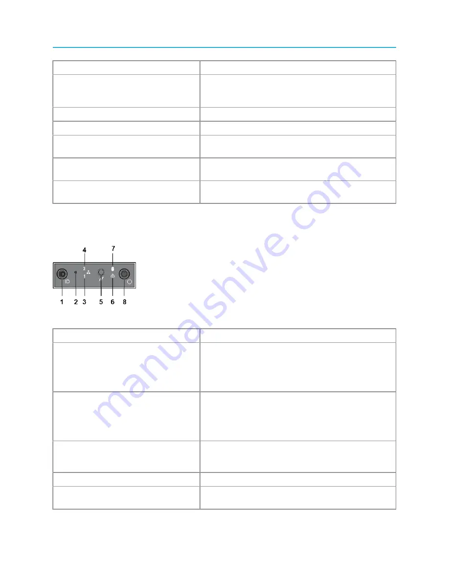
Control panel buttons and LED indicators
Some control panel buttons on the ContentBridge 4000 are recessed and require a tool to use them.
Figure 1-4: Control panel buttons and indicators
Component
Description
1. System ID button with integrated LED
The identification button can be used to locate a particular
system within a rack. When this button is pressed, the
ID LEDs on the front panel and on the back edge of the
server board (viewable from the rear panel) flash until the
button is pressed again.
2. Non-maskable interrupt (NMI) button
(recessed, tool required for use)
The NMI button can be used to put the server into a halt
state when diagnosing an issue. To prevent an accidental
system halt, the physical button is located behind the
Control Panel and is only accessible with the use of a
small tipped tool.
3. NIC 0 Activity LED
When a network link is detected, the LED will turn on solid.
The LED blinks when data is being sent or received over
the network.
4. NIC 1 Activity LED
5. System cold reset button (recessed, tool
required for use)
When pressed, this button initializes a hard system reset.
To prevent an accidental reset, the physical button is
9
Harmonic MediaGrid 5.0 Installation Guide


