


48
1019658 11/2014
5.9.1 Assembly of the Circular Spline
The Circular Spline must not be bended during the assembly. Therefore it is particularly important that the mounting base
of the Circular Splineis absolutely even and that the mounting base centering causes neither clamping strength nor radial
clearance.
Explanation:
A slightly deformed Circular Spline can result in irregular running characteristics. If a deformation of the Circular Spline is
suspected it should be verified whether the Circular Spline can rotate freely within its locating bore in the machine housing
without any friction. Even slight friction may be an indicator for a possible radial deformation of the Circular Spline. In this
case the tolerances of the machine housing and the Circular Spline must be checked.
For grease lubrication the Circular Spline teeth must be lubricated in accordance with illustration 43.1. For the correct
mounting please also see illustration 39.1.
Circular Spline Screws
Table 48.1
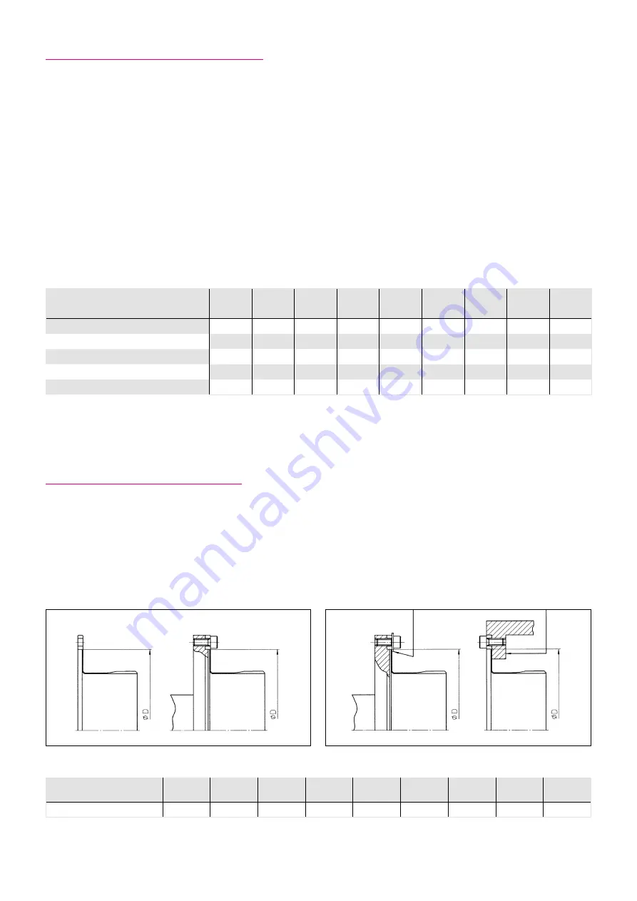
5.9.2 Assembly of the Flexspline
Care must be taken that the heads of clamping bolts, washers, nuts or clamping rings do not interfere with local flexing of
the Flexspline. Otherwise eventual failure will result.
For this reason, fastening elements must not enter the region which is marked by ø D. Please refer to illustration 48.2.
Illustration 48.2
Illustration 48.3
Size
14
17
20
25
32
40
45
50
58
Number of screws
6
12
12
12
12
12
12
12
12
Size of screws
M3
M3
M3
M4
M5
M6
M8
M8
M10
Pitch circle diameter [mm]
44
54
62
75
100
120
140
150
175
Clamping torque [Nm]
2.0
2.0
2.0
4.5
9.0
15.3
37
37
74
Torque transmitting capacity [Nm]
54
131
147
314
675
1150
2440
2620
4820
Right
Wrong
Table 48.4
[mm]
Size
14
17
20
25
32
40
45
50
58
ø D
48
60
70
88
114
140
158
175
203
The tables are valid for completely degreased pads (friction coefficient µk = 0.15) and metric socket head cap screws according to EN ISO 4762 in 12.9 quality,
untreated, oiled, with µtotal = 0.12.