16
3-90-70744R11_05/13
Special Instructions
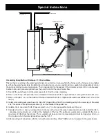
Hot Water Out
Cold Water In
Pressure
Relief Valve
Existing Water
Heater
Rear Of
Furnace
Automatic
Air Valve
Pressure
Relief Valve
(Must be within
2 feet of coil)
10 Feet Maximum
Drain
Valve
1
2
3
3
4
5
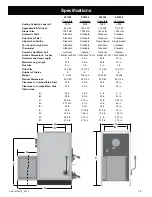
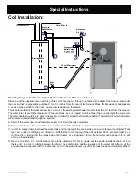
Plumbing Diagram For Thermo-Siphon Method - Maximum Distance = 10 Feet
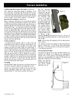
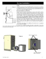
Place one of the supplied nuts on each leg of the coil Place the coil through the holes on the back of the furnace and ad ust
WKHQXWVVRWKDWWKHSLSHVVWLFNRXWDERXWóWRòLQFKHVIURPWKHUHDURIWKHIXUQDFH3ODFHWKHÀDWZDVKHUVDQGJDVNHWV
o er each pipe and tighten the nuts ou are now ready to run the piping
This simple method is the most economical Howe er the existing water heater must be less than 10 feet from the furnace
The water inlet where the Temperature / Pressure Relief al e is located must be higher than the top leg of the water coil
The water heater should be ele ated if necessary to allow for proper thermo-siphon action (The method by which hot water
will circulate automatically through the system )
A Shut off the water heater and the water supply to it Drain the tank completely
B Remo e the Temp / Presure relief al e and discard Install a short 3/4 in nipple and tee (1) along with a new relief al e
&UXQLQFRSSHUWXELQJEHWZHHQWKHZDWHUWDQNDQGWKHWRSOHJRIWKHFRLO,QVWDOODLQYHQWHOERZDQGDXWRPDWLF³ÀRDW
type” air ent (2) in the high point of the line Within 2 feet of the top leg of the coil install a 150 lb pressure relief al e
(5) Run 3/4 in tubing from the release exit of both relief al es downward (3) so the hot water can escape in the e ent
of an o erheat situation
D Remo e the drain al e at the bottom of the tank Install a short 3/4 in nipple and tee and re-install the drain al e to
the tee (4) Run 3/4 in tubing between the drain / tee combination and the lower leg of the water coil After all of the
FRQQHFWLRQVDUHVHFXUHGUH¿OOWKHZDWHUWDQN
7XUQRQWKHZDWHUKHDWHURQO\DIWHUWKHWDQNKDVEHHQFRPSOHWHO\UH¿OOHG
Coil Installation:
Содержание SF1500A
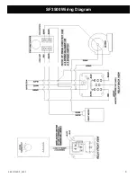
Страница 9: ...9 3 90 70744R11_05 13 SF3500 Wiring Diagram...
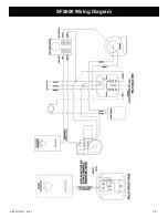
Страница 10: ...10 3 90 70744R11_05 13 SF2600 Wiring Diagram...
Страница 21: ...29 3 90 70744R11_05 13...

