background image

11

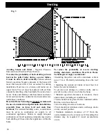
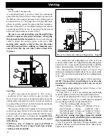
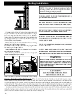
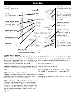
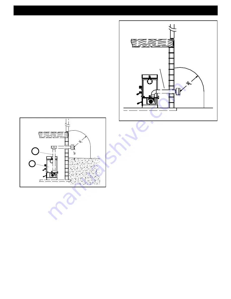
The  minimum vent configuration is a 90

o

 or Tee on 

a starter collar and a 24” length horizontal through an 

exterior wall.  A cap on the end should direct the flue 

gasses down and away from the structure. See Fig. 5. 

The  maximum  horizontal  length  is  18  feet.  The  

minimum termination height above the exterior grade 

is 18”. The maximum total length of any configuration 

is 30 feet*. 

* ( see venting graph on page 10 for exceptions )

NOTE: Cleanout Tee’s should always be used on the 

transitions to horizontal pipe to allow easy access for 

cleaning.

The venting graph allows for one(1) 90 deg. or Tee 

fitting in any configuration.

If more 90’s, T’s, or 45’s are needed, the total length 

must be adjusted to allow for the added restriction.

Up to four (4) additional 90’s, Tee’s, or equivalent 45’s 

can be  added as long as the overall length is adjusted 

in accordance with the values listed below.

( See the venting graph on page 10.)

Each Vertical ---- 90 deg. or T subtract 2.5 feet

Each Vertical ---- 45 deg.        subtract 1.5 feet

Each Horizontal - 90 deg. or T subtract 5.0 feet

Each Horizontal - 45 deg.        subtract 2.5 feet

Any exterior venting (vent pipe exposed to outside 

ambient temperatures) should be kept to a minimum, 

due to potential condensation problems.

This is especially important in high humidity cold 

weather climates, such as maritime areas, lake shores, 

and low river valleys.

Venting

venting

Venting

Use 4” pellet vent pipe only. 

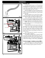
A combustion blower is used to extract the combustion 

gases from the firebox. This creates a negative pressure in 

the firebox and a positive pressure in the venting system 

as shown in Fig. 4. The longer the vent pipe and more 

elbows used in the system, the greater the flow resistance. 

Because of these facts we recommend using as few elbows 

as possible and 30 feet or less of vent pipe. The maximum 

horizontal run should not exceed 18 feet. 

Be sure to use wall and ceiling  pass through fittings 

(which are approved for pellet vent pipe ) when going 

through combustible materials. 

Be sure to use a starting 

collar  to  attach  the  venting  system  to  the  stove. 

The 

starting collar must be sealed to the stove flue collar  

with high temp silicone caulking or aluminum tape, 

and screwed into the stove flue collar at least three 

(3) places.

Fig. 4

-

+

Vent Pipe

4”  pellet  vent  pipe  (also  known  as  “PL”  vent)  is 

constructed  of  two  layers  with  air  space  between  the 

layers. This air space acts as an insulator and reduces the 

outside surface temperature to allow a minimum clearance 

to combustibles as low as 1 inch. In Canada the minimum 

clearance to combustibles is 3 inches. 

The sections of pipe lock together to form an air tight 

seal in most cases; however, in some cases a perfect seal 

is not achieved. For this reason and the fact that the boiler 

operates with a positive vent pressure, 

we specify that  

all joints within the structure should also be sealed 

with silicone.

NOTE:Use  only  4”  diameter  approved  PELLET 

venting system. Be sure to inspect and clean exhaust 

venting system frequently.

4” Type “L” or 

“PL” Vent pipe

This is the minimum venting configuration.

Fig. 5

Содержание PB 105

Страница 1: ...d understand this entire manual Consult your local authorities having jurisdiction Contact your municipal building department Fire department or other localauthorities before installing this boiler Lo...

Страница 2: ......

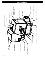
Страница 3: ...mperature Pressure Gauge Pressure Relief Valve Aquastat Well 1 1 4 FMPT Supply 1 1 4 FMPT Return Ash Door Firebox Door Access Cover To Hopper Swing Plate Knob Access Cover To Secondary Ash Chamber Bla...

Страница 4: ...Pellet Fueled Central Supplementary For Residential Use Standard s CAN CSA B366 1 M91 and UL 391 Note This appliance is also approved for installation into a shop WARNING RISK OF FIRE Hearth Home Tec...

Страница 5: ...plates pellet or corn burnpot front plate locks corn auger extensions ceramic inserts and ceramic insert plates 2 noise caused by minor expansion contraction or movement of parts 3 damage resulting fr...

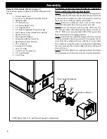
Страница 6: ...nuts and lock washers provided to the studs by removing the access cover on the secondary ash chamber Step 2 Place the combustion motor onto the flue tunnel weldment and tighten the 3 wing screws prov...

Страница 7: ...nstall 3 4 MPT pressure relief valve as shown 5 Install the 1 2 MPT aquastat well in fitting as shown then place aquastat in the well and fasten with a zip tie The aquastat sensor is located under the...

Страница 8: ...TO BE PERFORMED BY A QUALIFIED INSTALLER NOTE All installation clearances and restrictions must be adhered to NOTE Use only 4 diameter type L or PL venting system Be sure to inspect and clean exhaust...

Страница 9: ...ly when measured from the horizontal center line of the regulator 1 I The clearance to service regulator vent outlet must be a minimum of 6 feet 1 J The clearance to a non mechanical air supply inlet...

Страница 10: ...tion must be given to combustion air supply to all combustion appliances Failure to supply adequate combustion air for all appliance demands may lead to back drafting of those and other appliances wit...

Страница 11: ...used to extract the combustion gases from the firebox This creates a negative pressure in the firebox and a positive pressure in the venting system as shown in Fig 4 The longer the vent pipe and more...

Страница 12: ...ote has accumulated 3mm or more it should be removed to reduce the risk of a chimney fire This boiler may be used and installed into an existing masonry or Class A metal chimney Certain Canadian and L...

Страница 13: ...will build up blocking the intake air supply The OutsideAir knockout is located on the face of the Feeder Cover It is pre cut except for several small tabs There is also a filler plate screwed to the...

Страница 14: ...never be powered by the use of an extension cord The recommended high and low voltages are 130 V A C 60 Hz maximum high voltage and 113 V A C 60 Hz minimum low voltage The furnace will continue to ope...

Страница 15: ...nimize moisture and creosote it is strongly recommended that some form of temperature balance is incorporated into the return water system NOTICE When installing with the atmospheric conversion All of...

Страница 16: ...g the operation of the solid fuel boiler 5 Have provision for preventing or adequate water capacity within the boiler to prevent damage to the boiler from loss of circulation due to electrical power f...

Страница 17: ...TO DESIRED WATER TEMPERATURE NORMALLY NOT MORE THAN 120 DEGREES TEMPERED HOT WATER FOR SHOWERS AND FAUCETS Installation COLD WATER SUPPLY MIXING VALVE SET TO DESIRED WATER TEMPERATURE NORMALLY NOT MOR...

Страница 18: ...ETURN 1 1 4 THERMOMETER CHECK VALVE OR BACKFLOW PREVENTER IF REQUIRED THERMOMETER NOTE ALWAYS REFER TO THE INDIVIDUAL COMPONENTS RECOMMENDED INSTALLATION INSTRUCTIONS FOR THE PROPER MOUNTING POSITION...

Страница 19: ...oisture and creosote it is strongly recommended that some form of temperature balance is incorporated into the return water system NOTICE When installing with the atmospheric conversion All of the pre...

Страница 20: ...d pressure to the point of opening the relief valve or with the atmospheric conversion it may allow the water to boil and exit through the over flow of the atmospheric tank Both scenarios may create w...

Страница 21: ...ay not be possible to get a low draft reading in this range In this case a maximum low draft of 55 is acceptable The adjustment screw is through the small hole to the right of the Igniter Light See Fi...

Страница 22: ...es not flow properly through the feed system Size Pellets are either 1 4 inch or 5 16 inch 6 8mm in diameter Length should be no more than 1 1 2 inches 38mm Pellet length can vary from lot to lot from...

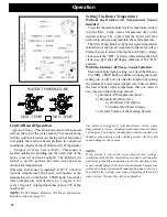
Страница 23: ...igniter Lighting Mode Selector Switched between Auto and Manual lighting Mode Selector Min Temp Dial Used to turn the boiler on or off and set the desired minimum operating temperature of the boiler S...

Страница 24: ...secondary ash chamber area and also in the venting system which could cause damage in these areas NOTE If the system is run at the lower temperature settings conditions of the firebox boiler tubes sec...

Страница 25: ...t 185 o 65 o 140 o 45 Min set at 140 o 60 o 145 o 40 55 o 150 o 35 50 o 155 o 30 45 o 160 o 25 o 40 o 165 o 20 o 35 o 170 o 15 o 30 o 175 o 10 o 25 o 180 o 5 o 20 o 185 o 0 o 15 o 185 o 0 o 10 o 185 o...

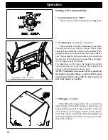
Страница 26: ...r swing plate open for easy access to the burn pot The burn pot can also be reached through the firebox door NOTE To minimize the amount of stress placed on the hopper swing plate hinges opening of th...

Страница 27: ...etting that works well for your application use that setting NOTE You know your feed rate is too high when The overheat safety feature is energized each time the heating zone demand turns off during a...

Страница 28: ...g the fire manually will not be necessary unless the igniter system fails Follow steps 1 through 5 of the instructions for automatic lighting 6 Flip the Igniter Switch Down into the MANUAL LIGHT posit...

Страница 29: ...r level according to the MAX TEMP dial setting Solid fuel burning appliances need to be cleaned frequently because soot creosote and ash may accumulate If you suspect a chimney vent pipe fire do the f...

Страница 30: ...on unless excessive buildup is noticed during scheduled cleanings There is a cover on the front of the burnpot to gain access to the air chamber The cover is held into place by two thumb screws Loosen...

Страница 31: ...les of flyash The flyash will collect in the exhaust venting system and restrict the flow of the flue gases Incomplete combustion such as occurs during startup shutdown or incorrect operation of the r...

Страница 32: ...g At this time you can scrape and clean the burnpot and fines cleanout area Open firebox door and vacuum ash from ledges and ash deflector You can also clean the firebox door viewing glass using a typ...

Страница 33: ...The exhaust probe sensing tip extends into this same area CARE MUST BE TAKEN NOT TO DAMAGE THE ESP DURING CLEANING Bending of the ESPwill make it difficult to remove if it should become necessary See...

Страница 34: ...FIRE HAS GONE OUT 1 No pellets in hopper 2 Draft setting is too low 3 Something is restricting fuel flow 4 Feed motor or combustion blower has failed 5 Power failure or blown fuse SMOKE IS VISIBLE CO...

Страница 35: ...ing the atmospheric conversion air bleeders and check valves may actually allow air into the lines Another reason it is important to have a licensed Plumber involved in each phase of your installation...

Страница 36: ...5 Y Hopper Lid Spring Latch 3 31 00927 Y 2 Control Board Plate Studded w label 1 10 09330 3 Control Board 1 00 06143 Y Control Knob Shaft 25 Sets 1 00 015605 Y Fuse 6 AMP Pkg of 5 3 20 49447 5 Y 4 Fee...

Страница 37: ...4 20 x 3 4 Pkg of 100 3 30 1112 100 Y Wing Nut 1 4 20 Pkg of 25 3 30 8011 25 Y 8 9 Access Plate Gasket only 3 44 72207 Y 8 10 Base Weldment 1 10 00250W 8 11 Ash Chamber Jacket Right Left of Comb Hole...

Страница 38: ...t Rod Qty 3 Req 2 00 01036 Y Cleanout Rod Repair Kit 1 00 72210 Scraper Rod Guide Qty 3 Req 3 50 72189 Y 16 4 x 4 Steel Box 3 20 52171 17 1 2 NPT Boiler Drain Pre 008341121 3 10 05060 3 4 NPT Boiler D...

Страница 39: ...5 Gasket Feeder Air Intake Pkg of 6 3 44 72224 6 Y 28 6 UL Feeder Air Intake 1 10 72222 28 7 Gasket Ultra Air Intake Pkg of 10 3 44 677160 10 Y 28 8 Ultra Feeder Weldment 1 10 72226S Y 28 9 UL Feeder...

Страница 40: ...036 Y 5 16 24 Grade 8 Yellow Zinc Finished Hex Nut Pkg of 50 3 30 8007 50 Y 5 16 24 x 3 4 Alloy Steel Black Oxide ButtonHeadCapScrew Pkg of 50 3 30 3018 50 Y Outdoor Air Extension 3 20 72181 Outdoor A...

Страница 41: ...U if system is satisfied Min Burn 1 1 pound per hour Max Burn 13 4 pounds per hour 8500 BTU per pound figures Electrical 120 VAC 60 Hz Combustion blower 1 4 AMP Auger motor 7 AMP Igniter element 3 6 A...

Страница 42: ...10 9 11 8 PART NO 3 90 72194A 7 WHITE EMPTY EMPTY RED BLACK YELLOW DK BLUE EMPTY GREEN YELLOW WIRE IS GROUND BONDED TO STOVE BODY CONTROL BOARD TCP 3 4 1 9 8 11 10 ESP TWISTED WIRE BROWN PLUGGED WHITE...

Страница 43: ...HITE GREEN YELLOW BLACK 3 8 FLEX CONDUIT RED WHITE WHITE BROWN 4 SQUARE JUNCTION BOX GREEN WHITE GREEN BLACK DARK BLUE GREEN WHITE WHITE 3 8 FLEX CONDUIT 120 VAC power by installer from control board...

Страница 44: ...hnologies Inc WARNING Risk of fire Do not operate with the flue draft exceeding 9 in Water Column 224Pa ATTENTION Risque de feu Ne fonctionnez pas avec l bauche deconduite de chemin e exc dant 9 colon...

Страница 45: ...45 Service Record Notes...

Страница 46: ...46 Service Record Notes...

Страница 47: ...47 Proudly Printed On 100 Recycled Paper...

Страница 48: ...rn Feed Adjuster back to the 4 setting 8 Turn the MAX TEMP dial to the desired temperature 9 Turn MIN TEMP dial to the desired settings 10 Flip the igniter switch to Auto The boiler will ignite if the...

Отзывы: