background image

9

USER’S GUIDE

PRODUCT INFORMATION

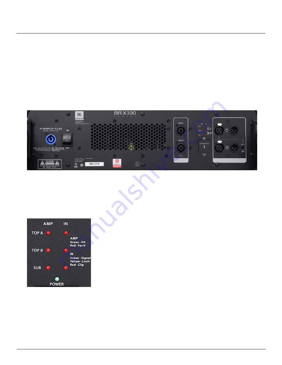
The module has a Neutrik 20A PowerCon power supply input connector for its power supply and ships with a 

power cord specific to the region it is purchased in. A power switch allows the module to be powered ON or OFF.
The module has 2 XLR-F input connectors: one for the subwoofer and one for the BRX308-LA tops. These 

connectors are wired in parallel to XLR-M connectors to enable daisy-chaining of input signal to other systems. 

There is a switch that allows for the subwoofer and tops to share the same input (INPUT Y) or use the subwoofer on 

a separate signal feed (DUAL). 
The module also has 2 Neutrik NL4 output connectors (labelled TOP A and Top B) for powering 2 x BRX308-LA on 

each output circuit.

The processing and power module has 7 multi-color LED Indicators used to provide feedback on power, input signal 

status and amplifier status.

Upon powering ON the unit, all the LED’s are lit red while the amplifiers and 

DSP boot up. Once the DSP and amplifier are ready to pass audio, the 

LED’s turn green.
The bottom-most LED—marked “POWER”—is lit green when the unit is 

receiving power and is in the ON state.
The left 3 LEDS show the amplifier status for each of the 3 pairs of amplifier 

channels that drive the SUB, TOP A and TOP B. When the LED’s are lit 

green, the amplifier is in the ready state and will pass audio through to the 

loudspeakers.
The LED’s light red to indicate a fault with the amplifier. Possible reasons 

could be thermal shutdown and extended period of output limiting. 
The LEDS on the right are used to indicate the status of input signal to each 

of the 3 pairs of amplifier channels that drive the SUB, TOP A and TOP B.
Green indicates signal presence (>=-40dBu), yellow indicates the onset of 

input limiting (+17dBu) while red indicates clipping (>=21dBu) of the input 

signal.
It is advised to set up the gain structure so that the yellow status lights only 

come on momentarily during maximum drive level from the mixer. Extended 

periods of limiting and clipping of the input signal will lead to failure of the 

loudspeaker components.

Содержание JBL Professional BRX 300 Series

Страница 1: ...B R X 3 0 8 L A B R X 3 2 5 S P B R X 3 0 8 A C C B R X 3 0 8 P M B R X 3 0 8 A F USER S GUIDE ...

Страница 2: ...System 7 BRX308 LA Dual 8 2 Way Line Array Element 8 BRX325SP Dual 15 Subwoofer Housing DSP Amplifier Module 8 SYSTEM WIRING INFORMATION 10 SYSTEM APPLICATION GUIDE 11 Option 1 Ground Stack Option 11 Option 2 Pole Mount Option 12 ACCESSORIES 13 BRX308 ACC Transporter Kit 13 BRX308 PM Storage 14 BRX308 AF Array Frame 15 SPECIFICATIONS 16 System Specifications 16 BRX308 LA Specifications 16 BRX325SP...

Страница 3: ...of generating sound pressure levels SPL sufficient to cause permanent hearing damage to performers production crew and audience members Caution should be taken to avoid prolonged exposure to SPL in excess of 90 dB 14 Read the System Rigging Manual before installation and use of the product 15 Do not block any ventilation openings Install in accordance with the manufacturer s instructions 16 Do not...

Страница 4: ... is based upon materials and practices common to North America and may not directly apply to other countries because of differing material dimensions specifications and or local regulations Users in other countries should consult with appropriate engineering and regulatory authorities for specific guidelines Correct use of all included hardware is required for secure system suspension Careful calc...

Страница 5: ...ystems must be inspected for fatigue at least annually or as required by local ordinance The inspection shall include a visual survey of the material for signs of corrosion bending or any other condition that may decrease the strength of the fastener Additionally any eyebolts shall be checked for possible spin out of the enclosure For all other hardware and fittings refer to the hardware manufactu...

Страница 6: ...5 subwoofer with power amplifier and DSP for entire system BRX308 ACC Accessory Kit Transport cart for 4 x BRX308 LA soft cover for cart soft cover for subwoofer speaker cables for system BRX308 AF Array frame for suspending up to 8 x BRX308 LA BRX308 PM Pole mount adapter kit ORDERING INFORMATION ...

Страница 7: ...2 x BRX 308LA each including linear phase FIR filters and dbx limiter suite for loudspeaker protection As such no external processing is required This system is primarily intended for ground stack use 4 x BRX308 LA 1 x BRX325SP and pole stacked 2 x BRX308 LA 1 x BRX325SP with the pole and adapter sold with the BRX308 PM Pole Mount Kit There is a third option of use as a flown system up to 8 x BRX3...

Страница 8: ...witches The BRX325SP has a rigging system that allows up to 4 x BRX308 LA to be mounted onto it for ground stacked applications Additionally a pole mount cup allows for up to 2 x BRX308 LA to be pole mounted onto the subwoofer using components from the optional BRX308 PM System The subwoofer also houses the DSP and amplifier module that powers the entire system The BRX308 LA has a simple yet highl...

Страница 9: ...e amplifiers and DSP boot up Once the DSP and amplifier are ready to pass audio the LED s turn green The bottom most LED marked POWER is lit green when the unit is receiving power and is in the ON state The left 3 LEDS show the amplifier status for each of the 3 pairs of amplifier channels that drive the SUB TOP A and TOP B When the LED s are lit green the amplifier is in the ready state and will ...

Страница 10: ... 2 x BRX308 LA tops The system can be driven in one of two modes 1 INPUT Y MODE In this mode a single output from the mixer feeds the entire system to drive both the sub tops 2 DUAL MODE In this mode both the sub and tops can be driven from different outputs of the mixer to enable additional control over the sub top balance of the system 2 Dual Mode 1 Input Y Mode From Mixer From Mixer From Mixer ...

Страница 11: ... the inter box angle to any of the values mentioned above align the bottom box s angle bar Lock hole to match with the desired angle value on the top box and lock it in place with the Quick Release Pin Figure 1 Angle Bar 0 shows an example angle bar setting of 0 When setting inter box angles of 8 and above the angle bar of the upper box may obstruct the angle bar from the below box from aligning w...

Страница 12: ...frequencies The pole mount adapter bar allows for the following angles for the first box mounted on it 0 2 3 4 5 6 8 9 10 11 and 12 The negative angles allow the first box to aim downwards and cover audience that is closer to the array To set the first box at the desired ve angle value align the desired value on the adapter bar to the bottom of the box and lock in place with the Quick Release Pin ...

Страница 13: ...peakers on the cart by first aligning the front and then the rear rigging points of the bottom loudspeaker to the attachment points on the cart as shown in Figure 4 4 Insert the QRP s and lock loudspeakers in place as shown in Figure 5 5 Follow the same process for the other two loudspeakers on the other side of the cart 6 Release the QRP s on the front top rigging points for the upper speakers as...

Страница 14: ...les in the sleeves as shown in Figure 9 with the threaded portion of the pole going in first 3 Release the two front QRP s on the pole adapter frame and slide into place as shown in Figure 10 4 Insert the QRP s through the clamps to lock the adapter in place as shown in Figure 11 The adapter holds the poles in place and prevents them from sliding out during transport Figure 9 Figure 11 Figure 10 A...

Страница 15: ...udspeaker as shown in Figure 13 2 Flip up the Angle Bar of the loudspeaker and use the QRP to secure the Angle Bar to the Array Frame by pinning through the LOCK hole on the Angle Bar as shown in Figure 14 This ensures a 0 sight angle for the first loudspeaker in the array 3 To attach the array frame to a BRX325SP Subwoofer place the Array Frame on the subwoofer so the frame aligns with the attach...

Страница 16: ...le ease of transportation The models are meant to be used together The specifications below are for shipping purpose only Frequency Range 10 dB 80 Hz 20 kHz Frequency Response 3 dB 100 Hz 19 kHz Max Rated SPL 136 dB System Components 2 x 8 LF 1 x 3 titanium compression driver Nominal Coverage H x V 110 x 12 each element vertical coverage is a function of inter box angles System Input Connectors 2 ...

Страница 17: ...17 USER S GUIDE Measured in a 2pi field SYSTEM FREQUENCY RESPONSE BRX308 LA Measured in a 4pi field using system DSP and amplifier module SYSTEM DIRECTIVITY SPECIFICATIONS ...

Страница 18: ...Issued 06 2020 8500 Balboa Boulevard Northridge CA 91329 USA USER S GUIDE BRX300 SERIES Website URLs China https jblpro com zh products brx300 Asia https jblpro com en asia products brx300 ...

Отзывы: