5
QUICK START GUIDE
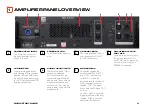
CONNECTING THE AC POWER CORD
Connect your amplifier to the AC mains power outlet using the supplied AC power cord. First, connect the PowerCon end of the cord to the PowerCon
connector on the amplifier. Then plug the other end of the cord to the AC mains.
WARNING:
The third (ground) prong of the supplied AC power cord connector is a required safety feature. Do not attempt to disable this ground
connection by using an adapter or other methods.
Make certain the AC mains voltage and current ratings are sufficient to deliver full power to the speaker system. The BRX300 Series amplifier is made to
operate at 230 VAC, 50 Hz ONLY.
POWER-UP PROCEDURE
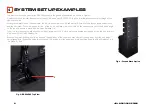
1. Connect the tops to the amplifier using 4-core cable wired to the NL4 connectors. Up to two tops may be wired in parallel to each output of the
amplifier (labelled ‘TOP A’ and ‘TOP B’). Connect the input source to the XLR inputs and select the appropriate drive mode (‘Dual’ or ‘INPUT Y’).
2. Toggle the amplifier’s POWER button to the ON position. The POWER indicator will light green and the amplifier will boot as long as sufficient mains
power is provided. During boot-up, all the other status LEDs are red. The LEDs turn off to indicate the amplifier is ready. If Input signal is present, the
Input LED’s will light green.
3. Turn your audio source up to an optimum level. The BRX300 Series amplifier will begin to limit input signals at +17 dBu, and the inputs begin clipping
at +21 dBu. To prevent damage to the system, it is recommended that you do NOT run the system in the limit or clip state for long periods.
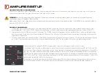
AMPLIFIER SETUP
3
The bottommost LED, labelled POWER, is lit green when the unit is receiving power and is in the ON state.
The left three LEDs show the amplifier status for each of the three pairs of amplifier channels that drive the SUB, TOP A and TOP
B. When the LEDs are lit green, the amplifier is in the ‘ready’ state and will pass audio through to the loudspeakers. If these LEDs
light red, it indicates a fault with the amplifier. Possible reasons could be thermal shutdown or extended period of output limiting.
The LEDs on the right are used to indicate the status of input signal to each of the three pairs of amplifier channels that drive the
SUB, TOP A and TOP B. Green indicates signal presence (≥-40 dBu), yellow indicates the onset of Input limiting (≥17 dBu), while
red indicates clipping (≥21 dBu) of the input signal.
It is advised to set up the gain structure so that the yellow status LEDs only light momentarily during maximum drive level from
the mixer. Extended periods of limiting and clipping of the input signal will lead to failure of the loudspeaker components.
Содержание JBL Professional BRX 300 Series
Страница 1: ...QUICK ST ART GUIDE...


