


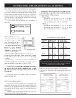


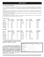


The above label on the Clarity's
burner system module indicates
that the unit is equipped to
burn natural gas.
The above label on the Clarity's
burner system module indicates
that the unit is equipped to burn
propane.
APPENDIX A
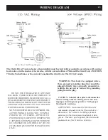
CAUTION: LABEL ALL WIRES PRIOR TO DISCONNEC-
TION WHEN SERVICING CONTROLS. WIRING ERRORS
CAN CAUSE IMPROPER AND DANGEROUS OPERATION.
VERIFY PROPER OPERATION AFTER SERVICING.
Converting the Clarity Direct Vent
from One Gas to Another in the Field
NATURAL GAS
PROPANE
NOTE: THE CONVERSION SHALL BE CAR-
RIED OUT IN ACCORDANCE WITH THE RE-
QUIREMENTS OF THE PROVINCIAL OR LOCAL
AUTHORITIES HAVING jURISDICTION AND IN
ACCORDANCE WITH REQUIREMENTS OF THE
CURRENT EDITION OF THE NATIONAL FUEL GAS
CODE, ANSI z223.1 or the CAN/CGA-B149 INSTAL-
LATION CODES.
Conversion kit Components
• 2 Burner orifices
• 1 Pilot orifice
• regulator assembly
• conversion instructions
• installer Fuel Label- (shown below)
• conversion Label-
Must be attached to valve upon
completion.
natural gas conver-
sion Kit, item #
1-00-08260
Propane conver-
sion Kit, item #
1-00-08280
Steps For Completing The Fuel Conversion.
Prior to installing the fuel conversion, remove the Glass
door and the log set, to gain access to the burner module.
remove the burner tubes by sliding to the left while lift-
ing upward. remove the burner cover plate and the tube
box top.
Step 1:
remove pilot hood with a 7/16” wrench. inside,
you will find and discard the Propane orifice. Install the
new Natural Gas orifice from the kit. Tighten the pilot
hood and assure proper alignment of the directional open-
ings.
Step 2:
using a 1/2 in. deep-well socket, remove the
three main burner orifices. Install the new orifices accord
-
ingly; Front = #47, Middle = #56, rear = #39. notice
the #56 that you removed from the front will be used in
the middle for natural Gas. apply a thread sealer to the
orifices prior to installing.
Step 3:
Using a small flat-blade screwdriver, remove
the three screws that hold the LP knob module in place.
remove the module and replace it with the natural Gas
module from the kit. see kit instructions.
Step 4:
Affix the conversion label to the valve so that any
future service tech etc... can plainly see that the valve was
converted.
Step 5:
Mark the appropriate fuel box on the unit label
using a permanent marker.
Step 6:
Affix the Installer Fuel Label in place of the exist
-
ing one.
Important: Perform a leak test upon completion
of the fuel conversion.
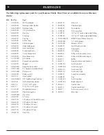
Содержание Clarity 929 DV
Страница 21: ...21 Safety lighting Label...
Страница 25: ...25 3 58 21 18 52 63 27 60 64 61 62 17 51 59 17 16 16 57 24 17 1 53 54 55 56 49 50 parts...
Страница 26: ...26 Clarity Burner Module Exploded View 38 36 47 12 13 14 39 48 42 46 40 41 31 32 33 52 53...
Страница 30: ...30...
Страница 31: ...31...
Страница 32: ......