5
Two Channel Amplifier
Harman Kardon
SIGNATURE 1.5
Cable with a gauge of 16 may be used for short runs of less
than ten feet. We do not recommend the use of cables with
an AWG equivalent of 18 or higher due to the power loss
and degradation in performance that will occur.
Cables run inside walls should have the appropriate
markings to indicate listing with UL (“CL-2/CL-3”), CSA
(“FT-4”) or appropriate safety agency standards that may be
required in your area. Questions about running cables
inside walls should be referred to your installer or a licensed
electrical contractor who is familiar with the NEC and/or the
applicable building or electrical codes in your area.
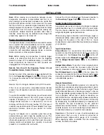
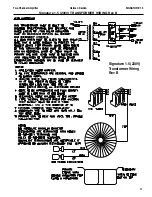
Two-Channel/Stereo Systems:
When installing a
two-channel (stereo) system, connect the positive (
+
) and
negative (
-
) terminals from the right and left speakers to the
matching terminals
on the rear panel of the 1.5. Make
certain that the
Bridge/Normal Switch
is in the
NORMAL position. When the 1.5 is used for
two-channel/stereo operation, speakers with an impedance
of no less than 4 ohms may be used.
Bridged Mono Applications:
To use the 1.5 as a
single-channel, mono amplifier, connect the (
+
) terminal on
your speaker to the (
+
) terminal on the
Channel Two
Output
on the 1.5. Connect the negative (
-
) terminal on
your speaker to the positive (
+
) terminal on the
C
hannel
One Output
.
Note: For mono applications, no connections are made to
the negative (
-
) speaker output terminals on the 1.5. Make
certain that the
Bridge/Normal Switch
is in the BRIDGE
position.
Important Note:
When the 1.5 is used in the Bridged Mono
mode, do not use speakers with an impedance of less than
8 ohms.
When making speaker connections, note that one
conductor of the speaker cable may have no markings or an
indication of (
-
) for negative polarity, and the other will have
a red line, brand-name markings, a colored thread or some
other positive-polarity indication (
+
).
The wire with the positive indication should be connected to
the red terminals on both the 1.5 and your speakers. The
negative wire should be connected to the black terminal on
the 1.5 and the speakers.
If bare wire is used for connections, strip approximately
3/4”(20 mm) of insulation from the end of each wire and
carefully twist the strands of each conductor together. Be
careful not to cut the individual strands or twist them off; for
optimal performance, all strands must be used.
Next, loosen the knobs of the speaker output terminals far
enough so that the cap moves back on its threads past the
holes at the rear of the terminal. Making certain that you
observe the correct polarity for the type of system being
installed (Stereo or Bridged Mono), pass the exposed wire
through the hole until the wire is visible from the bottom end.
Holding the wire in place, twist the cap back so that the
connection is secured. Do not overtighten or use tools, as
this may damage the plastic terminal cap or break the
delicate wire strands and decrease system performance.
Important Note:
When making speaker wire connections,
be certain that none of the strands from one lead touch any
other lead. This will cause a short circuit and may damage
your amplifier or speakers. Damage from short circuits
caused in this manner is not covered by the product
warranty.
Connections may also be made using spade lugs or
standard 4 mm OD banana plugs. Before using a
banana-type jack, make certain that the plastic screw caps
on the 1.5 are firmly tightened by turning them clockwise
until they are snug against the chassis. This will ensure that
the maximum surface area of the plug is in contact with the
jack. Once the wire has been attached to the banana plug
following the plug manufacturer’s instructions, simply insert
the banana plug into the hole provided on the rear of the
colored screw caps on the terminal posts. Be certain to
observe proper polarity.
Finally, run the cables to the speaker locations. It is highly
recommended that the length of cable connecting any pair
of speakers be identical. For example, make certain that the
cable length connecting left and right front or left and right
rear (surround) speakers is identical, even though one
speaker may be physically closer to the amplifier than the
other. Do not coil any excess cable, as this may become an
inductor that creates frequency response variations in your
system.
Connect the wires to the speakers, again being certain to
observe proper polarity. Remember to connect the negative
or black wire to the matching terminal on the speaker.
Similarly, the positive or red wire should be connected to the
like terminal on the speaker.
Note:
While most speaker manufacturers adhere to an
industry standard of using black terminals for negative and
red ones for positive, some manufacturers may not adhere
to this configuration. To ensure properly phased
connections and optimal performance, consult the
identification plate on your speaker terminals, or the
speaker’s manual to verify polarity. If you do not know the
polarity of your speaker, ask your dealer or installer for
advice before proceeding, or consult the speaker’s
manufacturer.
7
5
8
8
5
7


