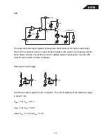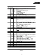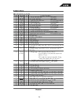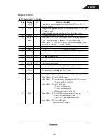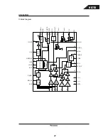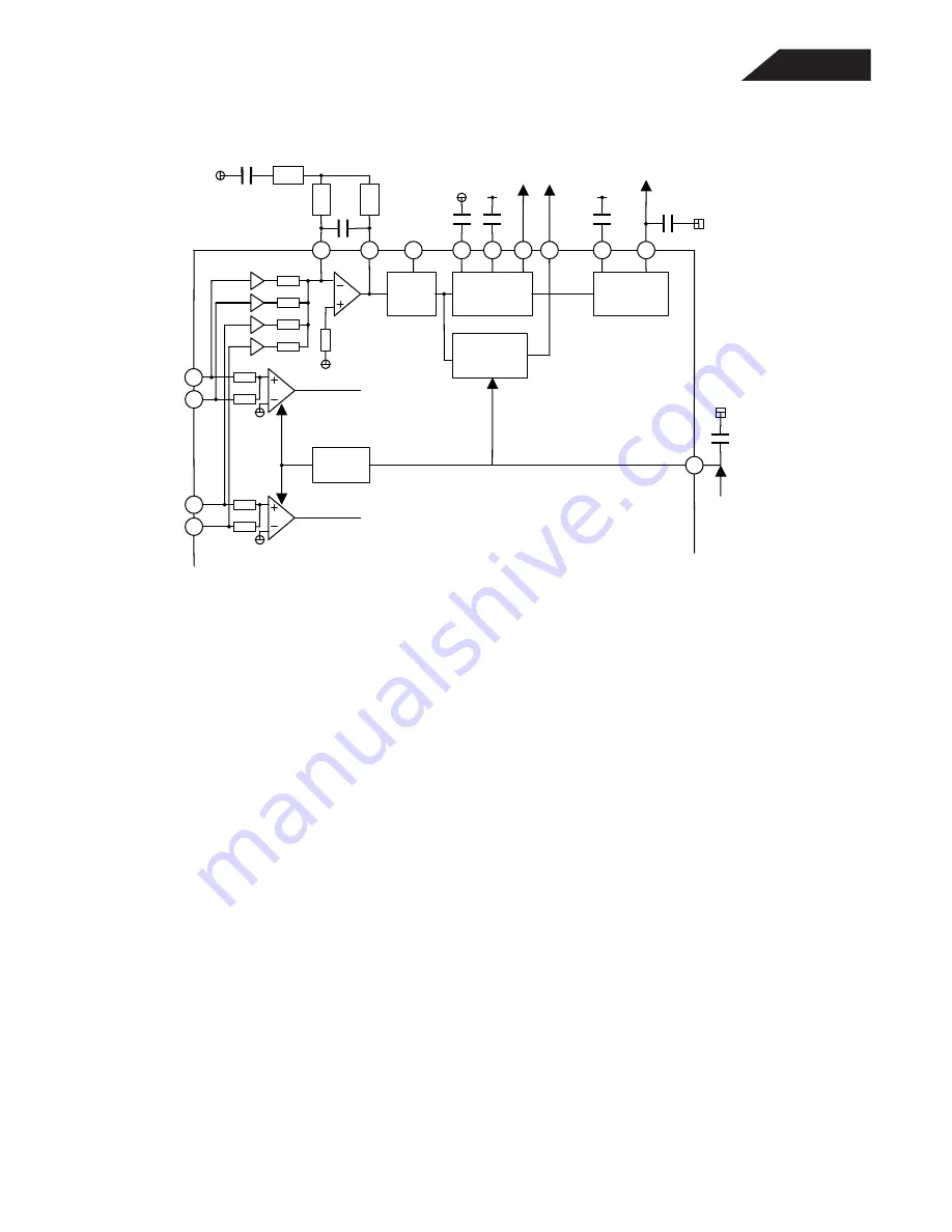
RF, EQ, AGC
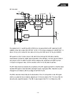
The signals A, B, C and D input from PDIC are composed into the RF signal by the RF
Addition Amp, then output from RFOUT of Pin 5. This Amp is designed so that RFOUT is
about 0.5 Vp-p for normal CD disc (about 0.4 Vp-p for CDR and 0.12 Vp-p for CDRW).
RF signal from Pin 5 is then input to the AGC block through the EQ block (the EQ
characteristic is fixed for single speed operation in this design). It is then gain-controlled
and output to Pin 10 ARF. The AGC block maintains the output level of ARF to about
1.0Vp-p for all types of disc. C38 connected to Pin 9 is for the AGC loop filter.
The RF Detection block detects the amplitude of the RF signal inputted from the EQ block.
Inputted RF signal is detected after passing through a high-pass filter. Detection level is
changed in accrodance with the voltage of GCTRL Pin 28.
The ENV detection block detects the fluctuation of the 3T-composition in the RF signal
which is needed for focus balance adjustment. C39 connected to Pin 11 forms a filter for
detecting the signal fluctuation. The ENV output signal from Pin 12 is filtered by C29.
36
34
GCTRL
V
GCTRL
C2
35
33
3
5
C35
C47
R27
R21
R20
6
EQ
AGC
8
9
10
17
RF
DETECTION
ENV
DETECTION
11
12
V
CC1
ARF
V
CC1
NRFDET
ENV
28
C29
C39
C28
C38
RFOUT
13
HD750
Содержание HD750
Страница 40: ...HD750 40...
Страница 48: ...HD750 48...
Страница 49: ...HD750 49...
Страница 50: ...HD750 50...
Страница 51: ...HD750 51...
Страница 52: ...HD750 52...
Страница 53: ...HD750 53...
Страница 54: ...HD750 54...
Страница 55: ...HD750 MAINBOARD 55...
Страница 56: ...HD750 CONTROL PANEL 56...
Страница 57: ...HD750 57...
Страница 58: ...HD750 REMOTE UNIT 58...
Страница 59: ...HD750 59...
Страница 60: ...DISPLAY PANEL PCB POWER SWITCH PCB HEADPHONES PCB HD750 60...
Страница 61: ...HD750 61...
Страница 62: ......
Страница 63: ......


