background image

1

1

2

2

3

3

4

4

5

5

6

6

7

7

8

8

D

D

C

C

B

B

A

A

Title

Number

Revision

Size

A3

Date:

2010/8/3

Sheet    of

File:

D:\HKTS210\DV1\INPUT_DV1.SchDoc

Drawn By:

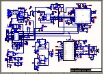
C47

104

+

C46

22uF/16V

D3.3V

C57

104

C58

104

+

C59

1uF/25V

+

C56

1uF/25V

R33

10K

SDOUT

1

SCLK

2

LRCK

3

MCLK

4

FILT+

5

AINL

6

VQ

7

AINR

8

GND

9

VA

10

U2

CS5343

3.3VAD

B5

BEAD-600

C54

180P

C55

180P

R38

100

R35

100

R37

100

R34

100

MCLK

SD0

LRCK

BICK

+7VA

+

C66

22uF/16V

C65

104

GND

3.3V

+7V

-7V

STB

R49

0

B9
BEAD-600

GND

B8
BEAD-600

B10

BEAD-600

1

2

XL1

12.288MHZ

C71

18P

C67

18P

C70

104

R50
100K

GND

MCU3.3V

2

4

3

5

U6

NC7SZ04M5X_NL

B12 120R

B11

BEAD-600

C68

OPT

C69

104

MCLK

R40
10K

+

C49

10uF/16V

MCU3.3V

+

C52

10uF/16V

MCU3.3V

INT1/P3.3

7

RxD/P3.0

2

TxD/P3.1

3

RST

1

GND

10

XTAL2

4

XTAL1

5

T0/P3.4

8

T1/P3.5

9

INT0/P3.2

6

P3.7/CEX0/PWM0

11

P1.0

12

P1.1

13

P1.2

14

VCC

20

P1.4/SS

16

P1.5/MOSI

17

P1.6/MISO

18

P1.7/SCLK

19

P1.3

15

U3

MPC82L52AT

C51
104

R42
10K

R41
10K

MCU3.3V

B14

BEAD

SDA

SCL

RESET#

B6 BEAD-600

B7

BEAD-600

TXD

MCLK

SDA

SCL

C50

104

MCU3.3V

GND

GND

GND

1

2

3

4

CN4

ISP

R45

100

MCU3.3V

GND

V

SS

1

RST

2

V

C

C

3

U4

STM809-3.3V

POWER GOOD

GND

TXD

1

2

3

CN3

EQ

GND

R43 0

R48

10K

LED

MCU3.3V

Hi
Lo

LED

ON

OFF

R51
10K

MCU3.3V

1

2

CN5

CON2.0-2

GND

22u/16

+

C34

22u/16

+

C39

22u/16

+

C42

C37

220P

C41

220P

C44

220P

R23

10K

R24

10K

R27

10K

+

5

-

6

O

7

U1B

TL072

3

2

1

8

4

B+

B-

U1A

TL072

R21

10K

C35

100P

C38

104

C43

104

22u/16

+

C45

R25

5K

C36

100P

R22

100K

22u/16

+

C40

R31

50K

R26

10K

GND

R36

4.99K 1%

R39

49.9K  1%

22u/16

+

C48

22u/16

+

C53

1

2

ZD1

3.3V

ON

AUTO

POWER ON MODE

PHASE

Bass Boostor

R28 10K

MCU3.3V

PWR MODE

PHASE

BASS

BASS

PHASE

PWR MODE

AUTO ON

AUTO ON

R46

0

GND

C61
104

C60
104

GND

C62
104

-7VA

STB

1

2

3

7

8

9

4

5

6

JK2

PHONE

R54

10K

MCU3.3V

GND

-7VA

+7VA

R55

22K

1

D1

ES1G

1

2

ZD2

3.3V

GND

C76
104

R56

22K

TRIGGER

TRIGGER

PLUG_DET

PLUG_DET

LO

HI

NO PLUG

PLUG IN

GND

LED

3

2

1

Q2

2N3904

PLUG_DET

TIGGER

PWR MODE

AUTO ON

STB

LED

0

1(AUTO)

1

0

1(AUTO)

0

0

1

1

0

0

0

0

1

1

0

0(ON)

X

X

X

1

0

1

1

X

X

0

1

1

0

AUTO OFF TIME=15 MIN

309A_PWRDN

EAPD#

R47

2.7K

GND

GND

+

C75

22uF/16V

C74

104

+3.3V

GND

+7VA

SW3.3V

R53

10K

C72

104

GND

VI

1

VO

5

G

N

D

2

EN

3

NC

4

U7

AP6209_3.3V

B13

BEAD-600

B4

BEAD-600

EN

VOUT

Hi
Low

0V

3.3V

+

C64

22uF/16V

R52

OPT

C63

104

C73

104

GND

GND

VI

3

VO

2

G

N

D

1

VO

4

U5

AP6209_3.3V

3

5

6 4

1

2

G2

G1

SW1

PWR

GND

GND

REVERSE

NORMAL

R29 10K

MCU3.3V

3

5

6 4

1

2

G2

G1

SW3

PHASE

GND

GND

ON

OFF

R30 10K

MCU3.3V

3

5

6 4

1

2

G2

G1

SW2

BASS

GND

GND

GND

4

L

5

R

3

GND

1

LFE

2

JK1

RCA-3P

2

3

1

VR1

1KA

RESET#

EAPD#

POWER GOOD

309A_PWRDN

SCL

SDA

SD0
BICK
LRCK
MCLK

HKTS2

1

0SUB

1

2

3

4

CN6

CON2.5-4

1

2

3

4

J1

CON2.0-4

GND

MCU3.3V

MCU3.3V

MMBT 3906

E

C

B

Q3

R57

10K

R59

4K7

R58

47K

GND

MCU3.3V

TXD

EAPD#

GND

MCU3.3V

LFE  1
NOR  0

TO LFE SW PCB

G

  S

C78

100P

GND

GND

GND

GND

GND

GND

GND

GND

GND

GND GND

GND

GND

GND

GND

R60

10

K

1

2

CN7

CON2.5-2

Harman Kardon

HKTS 20+30+60 Service Manual

Page 48 of 49

Содержание Cen-TS20/30

Страница 1: ...rnia 91329 CONTENTS HKTS 20 30 USER GUIDE 2 HKTS 60 with 200 SUB USER GUIDE 13 HKTS 60 with 210 SUB USER GUIDE 24 HKTS 20 SAT EXPLODED VIEW PARTS 36 HKTS 30 SAT EXPLODED VIEW PARTS 37 HKTS 30WQ SAT EX...

Страница 2: ...HKTS20 HKTS30 Designed to Entertain User Guide English Home Theater Speaker System 0165CSK HK HKTS20 and HKTS30 v6 indd 1 08 10 09 13 31 43 Harman Kardon HKTS 20 30 60 Service Manual Page 2 of 49...

Страница 3: ...ifier The speaker cables all use a color coding system to conform to the Consumer Electronics Association CEA standard This color coding system minimizes confusion when connecting the speakers especia...

Страница 4: ...HKTS200SUB s amplifier will turn on The HKTS200SUB s amplifier will turn off after the trigger signal ceases This will occur even when the Power On Mode Switch 3 is in the AUTO position Line Level LFE...

Страница 5: ...aker Subwoofer Left Surround Sound Right Surround Sound The two surround speakers should be placed slightly behind the listening position facing each other and ideally should be 5 6 feet 1 5m 1 8m fro...

Страница 6: ...se the terminal to secure the wire c Insert the conductor with the colored band into the speaker s red terminal and insert the other conductor into the speaker s black terminal A Push Down on Cap to O...

Страница 7: ...ing System on page 5 Each speaker wire included with your system has colored bands at both ends of the conductor and the subwoofer cable has purple connectors that correspond to the color of the HKTS2...

Страница 8: ...r and the center speaker to the corresponding speaker terminals on your receiver or amplifier In your receiver or preamp processor s setup menu configure it for Subwoofer ON and set the front left fro...

Страница 9: ...mplifier front left and right inputs connect the single ends of Y adapters not supplied to the receiver s or processor s left and right line outputs Connect one of the Y adapter s double ends to the H...

Страница 10: ...DC connect it to the HKTS200SUB s External Trigger Input Connector 4 If the component s trigger voltage connection has a 3 5mm mini jack you can use the supplied combination LFE trigger cable to make...

Страница 11: ...plays at low volumes but shuts off as volume is increased Make sure that all wires and connections between the receiver amplifier and the speakers are connected properly Make sure none of the speaker...

Страница 12: ...4 11 32 x 3 15 32 216mm x 110mm x 88mm Dimensions including stands H x W x D 11 25 32 x 4 11 32 x 3 15 32 299mm x 110mm x 88mm Dimensions H x W x D 4 11 32 x 10 11 32 x 3 15 32 110mm x 272mm x 88mm Di...

Страница 13: ...HKTS60BQ 230 Home theater speaker system User Guide English Deutsch Suomi Fran ais Italiano Espa ol Svenska Nederlands Harman Kardon HKTS 20 30 60 Service Manual Page 13 of 49...

Страница 14: ...speaker cables all use a color coding system to conform to the Consumer Electronics Association CEA standard This color coding system minimizes confusion when connecting the speakers especially when...

Страница 15: ...HKTS200SUB s amplifier will turn on The HKTS200SUB s amplifier will turn off after the trigger signal ceases This will occur even when the Power On Mode Switch is in the AUTO position Line Level LFE...

Страница 16: ...1 5m 1 8m from the floor An alternate location would be on a wall behind the listening position facing forward The surround speakers should not call attention to themselves while they re playing Expe...

Страница 17: ...ier A Push Down on Cap to Open Hole B Insert Bare Wire into Open Hole C Release Cap to Secure Wire 10 Slide the speaker onto the mount s wall section as shown in the illustration Pull any slack speake...

Страница 18: ...s that correspond to the color of the HKTS200SUB s LFE jack This system helps ensure that the speaker in each location is connected to the correct receiver or amplifier terminals In addition to the co...

Страница 19: ...iver or preamp processor Connect each satellite speaker and the center speaker to the corresponding speaker terminals on your receiver or amplifier In your receiver or preamp processor s setup menu co...

Страница 20: ...the supplied combination LFE and trigger cable to one of those outputs and to either of the HKTS200SUB s Line Level L R In Con nectors Use a second RCA cable not supplied to connect the other receiver...

Страница 21: ...ocessor or another audio video component has a trigger voltage connection that supplies between 3 and 30V AC or DC connect it to the HKTS200SUB s External Trigger Input Connector If the component s tr...

Страница 22: ...r operation of your receiver amplifier Check that the balance control on your receiver amplifier is not set all the way to one channel Check your receiver amplifier s speaker setup procedure to make s...

Страница 23: ...e 45Hz 20kHz 6dB Recommended Power 20 150 watts Impedance 8 ohms nominal Sensitivity 83dB 2 83V 1 meter Tweeter One 1 25mm CMMD Lite dome video shielded Midrange Dual 3 75mm flat diaphragm drivers vid...

Страница 24: ...HKTS 60BQ 230 Home Theater Speaker System Owner s Manual ENGLISH Harman Kardon HKTS 20 30 60 Service Manual Page 24 of 49...

Страница 25: ...he speakers to your receiver or preamp processor and amplifier The speaker cables all use a color coding system to conform to the Consumer Electronics Association CEA standard This color coding system...

Страница 26: ...al Trigger input 5 Use the mini plug of the supplied combination LFE and trigger cable to connect the External Trigger input to the trigger output of another compatible component Whenever a trigger si...

Страница 27: ...uld be 5 6 feet 1 5m 1 8m from the floor An alternate location would be on a wall behind the listening position facing forward The surround speakers should not call attention to themselves while they...

Страница 28: ...ll the way into the hole B Release the terminal to secure the wire C Insert the conductor with the coloured band into the speaker s red terminal and insert the other conductor into the speaker s black...

Страница 29: ...ation A Push Down on Cap to Open Hole B Insert Bare Wire into Open Hole C Release Cap to Secure Wire IMPORTANT Make sure the and bare wires do not touch each other or the other terminal Touching wires...

Страница 30: ...pass filtering follow the instructions in Connecting the Subwoofer to a Receiver or Preamp Processor With Line Outputs on page 10 Use the LFE purple connector of the supplied combination LFE and trig...

Страница 31: ...puts that are not connected to amplifier inputs connect the LFE purple connector of the supplied combination LFE and trigger cable to one of those outputs and to either of the HKTS 210SUB s Line Level...

Страница 32: ...n that supplies between 3V and 30V AC or DC connect it to the HKTS 210SUB s External Trigger Input 5 If the component s trigger voltage connection has a 3 5mm mini jack you can use the supplied combin...

Страница 33: ...kwise to decrease the subwoofer s volume Subwoofer Adjustments Phase The Phase Switch 0 determines whether the HKTS 210SUB s piston like action moves in and out in phase with the satellite speakers If...

Страница 34: ...ck your receiver amplifier s speaker setup procedure to make sure that he speaker in question has been enabled and its volume level has not been turned all the way down Make sure that all wires and co...

Страница 35: ...ower 20 150 watts Impedance 8 ohms nominal Sensitivity 83dB 2 83V 1 meter Tweeter One 1 25mm CMMD Lite dome video shielded Midrange Dual 3 75mm flat diaphragm drivers video shielded Dimensions includi...

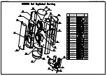
Страница 36: ...Harman Kardon HKTS 20 30 60 Service Manual Page 36 of 49...

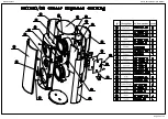
Страница 37: ...Harman Kardon HKTS 20 30 60 Service Manual Page 37 of 49...

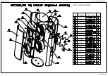
Страница 38: ...Harman Kardon HKTS 20 30 60 Service Manual Page 38 of 49 NOTE WHITE VERSION...

Страница 39: ...Harman Kardon HKTS 20 30 60 Service Manual Page 39 of 49...

Страница 40: ...Harman Kardon HKTS 20 30 60 Service Manual Page 40 of 49 NOTE WHITE VERSION...

Страница 41: ...o s s o r C m a o f g n i p m a D e g d i r B r e t e e w T r e t e e w T l a n i m r e T e l l i r G r e v o C m o t t o B e s a B d n a t S d a p r e b b u R o g o L w e r c S e l o P d n a t S e l...

Страница 42: ...002 BPEA00006 0001 HSPA50352 4300 1 2 1 2 1 1 2 1 2 1 2 2 6 8X 3 2XL9 0 ABS HB 15XH9 0MM SILICON 60 65 BT4 0XL20 Steel 1018 L70XW7 2XT0 5 CHROME PLATING L304 8XW266 7XD266 7 MDF E1 BT3 0XL12 Steel 101...

Страница 43: ...WIRE TERM 2P 380mm RED BLACK PC 1 XGLA00102 0001 704 BLACK SILICON GLUE 1pcs 90g PC XAD050010 0001 DOUBLE SIDE TAPE W10mmxL50M RL RL IVEA00178 0001 EVA PAD PC 1 IVEA00152 0001 SPONGE L700 W30 T3 0 GR...

Страница 44: ...C3602 P0C3701 P0C3801 P0C3902 P0C4002 P0C4101 P0C4501 P0C4602 P0C4701 P0C5002 P0C5102 P0C5201 P0C5302 P0C5402 P0C5501 P0C5701 P0C5801 P0C5901 P0C6002 P0C6102 P0C6201 P0C6302 P0C6402 P0C6602 P0C6702 P0...

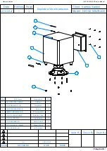
Страница 45: ...BAE Rubber Feet 4 6 316 AG 00557 E LogoBadge 2 7 413 000 05591 E Static Label 2 8 321 ABS 05141 0BAE Plastic Feet 4 9 162 A025D023 E LED Cable 1 Dsgn By Check By Editions Page Exploded View Instructio...

Страница 46: ...5D009 E 2 5 CONNECTOR 162 A013D011 E 3 96 HOUSING 3 205 0 8T TERMINAL 162 A042D002 E 3 96 HOUSING 3 250 250 205 TERMINAL 163 11009 E NYLON TIE 100MM CLEARCOLOR 180 P3024DB E ROCKER SIWTCH 3024 DB 302...

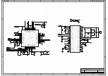
Страница 47: ...F R8 0 B3 BEAD 600 C1 104 C20 104 VDD 3 SDI_12 9 SDI_34 8 GND 13 RESET 15 SDI_56 7 SDA 18 SCL 19 SA 17 MVO 1 VDD 28 XTI 20 GND 27 NC 22 PLLB 16 FILTER_PLL 21 GNDA 23 GND 45 NC 46 OUT2_B 47 OUT2_A 48 O...

Страница 48: ...R21 10K C35 100P C38 104 C43 104 22u 16 C45 R25 5K C36 100P R22 100K 22u 16 C40 R31 50K R26 10K GND R36 4 99K 1 R39 49 9K 1 22u 16 C48 22u 16 C53 1 2 ZD1 3 3V ON AUTO POWER ON MODE PHASE Bass Boostor...

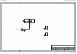
Страница 49: ...Date 2010 8 3 Sheet of File D HKTS210 DV1 LFE_SW SchDoc Drawn By LFE NORMAL 3 5 6 4 1 2 G2 G1 SW100 INPUT GND GND GND TO MAIN PCB G S 1 2 3 4 J100 CON2 0 4 GND 1 2 3 4 J101 CON2 0 4 GND 1 2 CN100 CON2...

Отзывы: