background image

43

NO

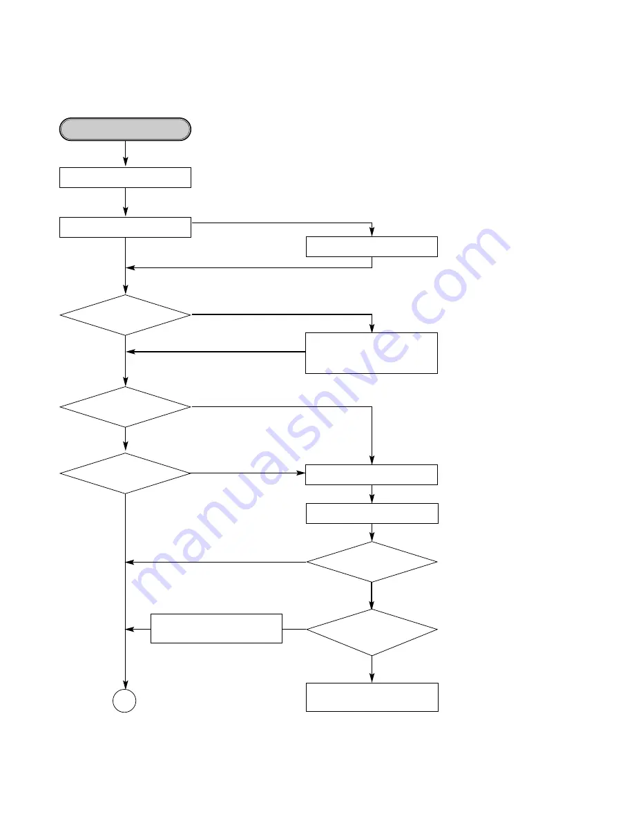
• Check the communication Iines

between IC203 and IC201.

• Check and replace that.

Writing Part Check.

Does the unit

becomes stand-by mode to

record/dubbing?

YES

NO

Eject Tray.

Go to “ALPC Logic Circuit Check”.

Dose Writing finish 

without any error?

YES

NO

NO

Go to “BETA Measurement
Circuit Check”.

Check the connection of IC201
pin 187 and replace IC201.

Is the written file 

read nomally?

Is the re-written file 

readed nomally?

Is

ROPCSH input signal 

Pulse when CD-R writing

(IC301 pin 38)

YES

YES

Refer “Laser is abnormal”.

Load tray with CD-R/RW Disc.

Start Recording or dubbing.

OK

YES

Содержание CDR 26

Страница 1: ...ROLS 7 FRONT PANEL DISPLAY 9 REAR PANEL CONNECTIONS 11 REMOTE CONTROL FUNCTIONS 12 INSTALLATION CONNECTIONS 14 BASIC TROUBLESHOOTING GUIDE WIRING DIAGRAMS 17 BLOCK DIAGRAMS 19 DETAILED TROUBLESHOOTING GUIDE 24 WAVEFORMS 47 EXPLODED VIEWS 49 MECHANICAL PARTS LIST 52 ELECTRICAL PARTS LIST 54 PCB DRAWINGS 71 SCHEMATIC DIAGRAMS 74 ERROR MESSAGES 16 harman kardon Inc 250 Crossways Park Dr Woodbury New ...

Страница 2: ... External Source Source 10dB Recording Dynamic Range 90dB Recording THD 0 01 0dB Analog Input Sensitivity 330mV RMS 47kΩ 0dB Digital Inputs Direct Recording 44 1kHz 100 ppm min General Power Requirement 110 240 VAC 50 60Hz Power Consumption 20 Watts Dimensions Width 17 5 16 440mm Height 4 7 16 112mm Depth 13 15 16 355mm Weight 13 lb 5 8kg Depth measurement includes knobs buttons and connection jac...

Страница 3: ...ched 4 Laser beams may damage the eyes Absolutely never permit laser beams to enter the eyes Also NEVER switch ON the power to the laser output part lens etc of the pick up if it is damaged 5 Cleaning the lens surface If there is dust on the lens surface the dust should be cleaned away by using an air bush such as used for camera lens The lens is held by a delicate spring When cleaning the lens su...

Страница 4: ... replacing a component part first disconnect the power supply lead wire from the unit 2 All equipment measuring instruments and tools must be grounded 3 The workbench should be covered with a conductive sheet and grounded When removing the laser pick up from its conductive bag do not place the pick up on the bag This is because there is the possibility of damage by static electricity 4 To prevent ...

Страница 5: ...assembly 3 Use only a grounded tip soldering iron to solder or unsolder ESD devices 4 Use only an anti static solder removal device Some solder removal devices not classified as anti static can generate electrical charges sufficient to damage ESD devices 5 Do not use freon propelled chemicals These can generate electrical charges sufficient to damage ESD devices 6 Do not remove a replacement ESD d...

Страница 6: ...c has started playing and without it the CDR 26 cannot begin a recording This is outside of our control as some manufacturers design products this way to prevent digital copies from being made Should you find that a digital recording cannot be made from an external playback source you may always use an analog connection to make the copy by pressing the Input Select Button on the front panel or rem...

Страница 7: ...ore information on dubbing Speed Press this button to select the recording speed for internal dubs See page 19 for more infor mation on selecting the proper speed Track Increment Press this button during recording to insert a new track marker at that point in the recording The current track number will be incremented by one Erase Press this button to erase one or more tracks or the entire contents...

Страница 8: ...ton to select the input source analog or digital for recording See page 20 for more information on input selection Ù Record Deck Time Display Select Press this button to cycle through the time display options for the Record Deck See page 17 for more information on the time display ı Information Display The indicators in the Information Display provide status reports on the oper ation of the CDR 26...

Страница 9: ...ital source connected to one of the optical inputs is being recorded See page 20 for more infor mation on source selection C Analog Indicator This indicator lights when an analog source is being recorded See page 20 for more information on source selection D Front Panel Input Indicator This indicator lights in conjunction with the Coaxial Digital Indicator A or the Optical Digital Indicator B when...

Страница 10: ...playing in either deck 3 or S Time Indicators These indicators light in conjunc tion with one of the time indicators TUVW to show which of the time status modes is active T Remaining Time Indicators These indicators light when the Information Display Y shows the time remaining on a disc U Recorded Time Indicator While a recording is in progress and up until a CD R or CD RW disc in the Record Deck ...

Страница 11: ...igital input should only be connected to digital input or output jacks Even though it uses the same RCA type connector as standard analog audio connections DO NOT connect it to conventional analog input or output jacks Optical Digital Input This jack accepts the digi tal audio input signal from a compatible digital audio product and should be connected to the optical digital output on a CD or DVD ...

Страница 12: ...isplay Control 30 Power Off 31 Continuous Play 32 IMPORTANT NOTE Some of the remote s func tions including Play Pause Stop Search Next and Previous Track are shared between the two decks Always remember to press the CDP Select Button d to use the remote to control the Play Deck or press the CDR Select Button to control the Record Deck When you press one of these buttons an indication of CDP or CDR...

Страница 13: ...finalization process is complete CD R or CD RW discs may not be played on conventional CD machines See page 21 for more information on finalization p Numeric Keys Press these buttons to access a specific track for playback or during the programming process See page 18 for more information on pro grammed playback q Speed Select Press this button to select the recording speed for internal dubs See p...

Страница 14: ...emble those of a standard tape recorder this may make it easier to select it as an input on your receiver or pre amp Connect the Analog Output Jacks to the Play In jacks of a Tape or Aux input on your receiver or preamp Connect the Analog Input Jacks to the Tape Rec Out jacks on your receiver or preamp To play the output through the digital decoder in your receiver or an external processor connect...

Страница 15: ...Remote Connections If the CDR 26 is installed behind a cabinet or other obstruction that may block the path between the front panel Remote Sensor ˆ and the location where you will use the remote an optional external IR sensor may be used Connect the sensor to the Remote IR In Jack on the rear panel This jack may also be connected to the IR Output jack of another compatible Harman Kardon component ...

Страница 16: ... record related button has been pressed when a Unfinalize the disc to add tracks to a CD RW disc finalized disc is in the Record Deck Replace the disc with a blank CD R or CD RW disc A record related button has been pressed when a Replace the disc with a blank CD R or CD RW disc standard CD is in the Record Deck DATA DISC A non audio CD ROM or a CD Video disc has been Only CD Audio and DTS discs w...

Страница 17: ...RO F_DOUT CS_DAC SCK_DAC DST_DAC GND DUB_SEL PWR_MUTE EXT_RMC DAC_RST LEVEL_SEL LEVEL_IN GND GND W V U H HU HU HV HV HW HW H GND SLDIN_SW1 13 22 22 1 1 1 30 30 6 1 1 8 1 1 8 12 1 1 12V GND 5 2VA GND A 8VA 8VA GND D 5VD 21VA 26VA 30VA D_GND 5VU A_GND 5VD D_GND 5 2VA 3 3V PWR_CTRL 8VA 12 17 1 1 6 1 3 3 1 3 1 3 1 20 1 3 1 1 F T T F GND VC VCC F E C B D A LD WD WR RF NC GND DIG IN VCC GND OPT IN HP_R ...

Страница 18: ...er Servo DSP Decoder FPGA DAC ADC U COM For CD RW U COM For CD P Servo DSP ENC DEC DRAM Drive RF Amp Drive RF Amp SRC FLD FLD Driver Key Expander CPLD ANALOG OPTICAL COAXIAL MD MD S W S W Expander CD RW CD P I O AK4382 AKM AK5380 AKM ...

Страница 19: ...4H04 Buffer H P OUT Buffer RMCN Jack Tr Analog R Out Analog L Out Analog R In Analog L In Coaxial Out Coaxial In Optical Out Optical In Front REC Vol DA_MCK DA_BCK DA_LRCK DA_DATA AD_MCK AD_BCK AD_LRCK AD_DATA DIG_IN F Out digital out LEVEL IN LEVEL SEL EXT RMC OPTICAL IN C D R W ...

Страница 20: ...0 IC402 LRCK 144 DATA 143 BCK 145 D OUT 146 IC201 33M 149 33M IC408 6 33M 13 63 LRCK 65 DATA 64 LRCK 36 D OUT 28 LRCK 29 DATA 27 BCK 32 D OUT LRCK 42 DATA 49 BCK 51 DA MCLK 55 4 LRCK 3 DATA 2 BCK 1 MCLK IC510 IC7V2 DAC 50 MLCK SRC IC502 4 TXP 26 RXP D OUT D OUT 41 RXP 66 TXP 66 ...

Страница 21: ... 11MCLK 9 AD DATA IC510 IC7V2 DAC SRC IC502 26 RXP Rear D IN Coaxial D IN 36 RXP 66 2 HD 0 19 HD 15 Rear Optical IN Opt IN 37 Front D IN Coaxial Front Optical IN IC411 IC406 F D IN 37 26 S W OUT 13 3 10 6 3 5 Buffer 46 LRCK 44 DATA 45 BCK LRCK 17 BCK 16 DATA 18 LRCK 12 BCK 13 DATA 14 69 LRCK 70 BCK 68 DATA ...

Страница 22: ...Da_src Dout_src Rec_src Src_src Ain A D AK5351 D A AK4393 Rear Vol AES3 ATAPI Analog CDP 3062 u com 32K SDRAM HOST I F AD_clk_src Cdp_cdr_src 33 8688MHz Lrck clk Audio Data Control Signal Rec Start U com I F CDP I2S CDRW I2S SRC I2S DA_CTRL Level Meter Relay Opt Div MAS3507D I2s_mode Da_clk_src 11MHz CDP ATAPI Process Block Diagram of IC510 ...

Страница 23: ... atapi 3 atapi 11 atapi 4 atapi 10 atapi 5 atapi 9 atapi 6 atapi 8 atapi 7 GND cs1_b test_mode mclk_in reset rw_dout D_out da_lrck1 da_clk da_data dac_mclk VDD GND src_lrck src_clk src_data ad_data ad_mclk F_opt_in test_in GND fpgacs_1 sclk_1 sdatao_1 da_pcs da_pclk da_pdata p_clk p_lrck p_data p_dout sdt_dac sck_dac cs_dac GND VDD F_coax_in ad_lrck ad_clk R_coax_in R_opt_in 5 10 15 20 25 30 35 40...

Страница 24: ...ad in Operation 2 Trouble List Circuit In the Initial Lead in Operation Mode A Pick Up doesn t move to the inner track B Pick Up lens doesn t move up and down C Disc doesn t rotate D The Laser RED of Pick Up doesn t light E TOC isn t read ...

Страница 25: ...ES Check C116 C117 L110 Vcc is supplied at IC104 pin1 3 and IC102 pin1 Check all Vcc line Open each line and check again Check power control Line Check connector and 5V line 3 No power D106 anode oscillate Normally Check the primary power part Check IC102 104 application Q107 Q102 Emitter are ok ...

Страница 26: ... Check IC802 Reset IC FLD heater Vcc is OK about 4V Between CN803 pin 1 and 4 IC801 pin6 is High Reset FLD CLK DATA CS is IC801 pin 7 8 15 OSC is appear in pin3 4 IC801 Replace IC801 Check connector CN803 PN401 and IC401 control lines NO Check IC401 and Reset line Check X801 4 FLD No Display 34V is OK IC801 pin60 ...

Страница 27: ...5 Troubleshooting Guide In the Initial Lead in Operation Mode 27 IC407 IC407 IC405 IC405 IC405 IC402 IC402 IC405 5 6 9 10 IC402 IC402 IC405 12 W 13 V 14 U IC402 IC402 IC405 FAO 92 4 95 ...

Страница 28: ...28 IC403 IC403 2 8 IC402 ...

Страница 29: ...C7V2 pin 1 2 3 4 YES NO YES YES Check connector PN501 CN701 IC510 output signals are right IC510 pin 42 49 51 55 Main clock is ok IC510 pin50 YES Change IC510 IC408 pin6 signal is ok YES Check MCLK path Check IC408 NO Check there path Input signals are right IC510 pin 63 64 65 YES YES YES YES CDP DSP IC402 pin47 48 49 ard right Check IC402 control line ...

Страница 30: ...No Audio Current Deck is CDR YES YES YES YES Check IC510 control path Check signal path between IC201 IC510 IC510 CDRW input signals are right pin27 28 29 IC201 signals are right IC201 143 144 145 Check IC201 cotrol path CDP is right ...

Страница 31: ... operating is abnormal YES NO Does Pick up move to inside Go to Sled operating is abnormal YES NO Does Spindle Motor rotate in a moment Go to Spindle opreating is abnormal YES NO Does Lens move Up Down YES Does Laser turn on Go to Focus Actuator operating is abnormal YES NO Go to Laser is abnormal NO OK After eject tray Inset CD Disc and reloading Does Disc stop Go to Spindle control is abnormal 1...

Страница 32: ...e the IC320 M62352 Check the communication line between IC304 and IC203 MICOM Check the Tray Connector PN302 Check the Motor Line and Motor NO NO Is there Tray drive voltage output IC303 pin36 37 YES YES YES Check the connection of IC303 Pin100 NO Replace the IC303 NO Is TRAY_MUTE signal L IC303 pin41 When PN302 is open Is there Tray drive signal output ...

Страница 33: ...here Sled control signal output IC203 pin 84 85 Is there Sled drive voltage input IC303 Check the connection of IC203 pin 84 85 YES YES YES Check the connection of IC203 Replace the IC303 Is there Sled drive voltage output IC303 pin 5 6 9 10 Is Act_Mute signal L IC303 Pin41 YES Replace the IC303 OK ...

Страница 34: ...IC303 Check the spindle Connector PN304 Replace the Spindle Motor NO Spindle operating is abnormal Is there Spindle control signal input IC303 pin 26 YES YES YES Is there Spindle control signal output IC306 pin 7 YES Is there DMO signal input IC306 pin5 Is there Spindle drive voltage output IC303 pin 12 13 14 Is SPNON signal H IC303 pin 263 YES Is there a SPNFG signal input IC203 pin 95 YES Replac...

Страница 35: ...ES YES Is Act_Mute signal L IC303 pin 41 Replace the IC303 BA5983 Check the connection of PN301 Pin 1 4 Check the Pick up Connector Replace the Pick Up Is there Focus Search drive voltage output IC303 pin 34 35 NO NO Go to Focus Servo is unstable Replace the IC301 CXA3558R NO Spindle control is abnormal 1 Does FOCUS Servo operate normally YES YES YES Is there a output normally IC301 pin 67 68 Repl...

Страница 36: ... Go to Track servo is unstable Does Tracking Servo operate normally YES Go to Disc recognition is abnormal NO NO Go to RF output is abnormal Spindle control is abnormal 3 Is there WBLIN signal input IC201 pin 132 Is there ATFM signal output IC301 pin 23 YES Replace the IC301 CXA3558R NO Replace the IC201 OTI 9790 Is there DMO signal output IC201 pin 2 YES Go to Spindle operating is abnormal ...

Страница 37: ...C203 MICOM Go to Track Servo is unstable NO NO Go to Laser is abnormal Check the PICK UP FFC Replace the PICK UP RF output is abnormal Is there PICK UP A B C D output normally PN301 pin 8 9 14 15 Is RRF signal output normal IC301 pin 82 First Recognition try Over 1 7 Vpp Second Recognition try Over 0 5 Vpp YES NO Check the connection between PN301 and IC301 Replace the IC301 CXA3558R OK ...

Страница 38: ...nal output normal in Focusing ON and Tracking OFF IC301 pin57 Is PICK UP E F G H output normal PN301 pin 16 7 13 10 YES Check the IC301 CXA3558R Go to RF output is abnormal NO Check the IC1306 Is TE signal input normal in Focusing ON and Tracking OFF IC201 pin198 YES NO Replace the IC201 OTI 9790 Is there TAO signal output in Tracking ON IC201 pin 208 YES Check the Driver IC IC303 and P U referrin...

Страница 39: ... Check and replace the PN301 PICK UP YES NO YES Check the P U connector and then replace the P U YES YES YES YES Normal E Execute E LD On of How to use Test Tool Dragon VRDC Lop Read Mode PN301 Pin 32 ENBL H IC301 Pin 5 RREF 0 8 0 3V IC301 Pin 99 FPDO 2 9 0 3V Check the connection of IC301 pin 4 Check and replace the IC301 VRDC NG Execute D LD Inspection of How to use Test Tool Dragon PN301 Pin 25...

Страница 40: ...e IC P U connector and replace the P U IC301 Pin 99 FPDO 2 9 0 3V YES YES PN301 Pin 27 VWDC1 1 2 0 8V YES NO Normal F Execute E LD On of How to use Test Tool Dragon VWDC 1 Loop PN301 Pin 32 ENBL H PN301 Pin 31 W XR H IC301 WREF 0 5 0 2V Check the connection of PN304 pin 19 Check and replace the PN301 PICK UP VWDC NG Check the connection of IC301 pin 8 Check the connection of IC304 pin 13 Check and...

Страница 41: ...f IC207 pin 18 and 34 Check and replace the IC207 CPLD YES YES NO Check the connection of IC304 pin 19 Check and replace the IC304 DAC YES YES G Execute E LD On of How to use Test Tool Dragon VWDC 2 PN301 Pin 30 ODON H PN301 Pin 31 W XR H PN301 Pin26 VWDC2 1 0 0 2V Check the P U connector and replace the P U ...

Страница 42: ... CD RW YES YES Remove the Dust Fingerprint and if the disc has long width Scratch change it Does the disc have any Dust Scratch Fingerprint NO NO Eject Disc Go to Writing Part Check Finalized Disc YES If CD R disc use new CD R disc If CD RW disc erase the disc Nomal Case ...

Страница 43: ... Logic Circuit Check Dose Writing finish without any error YES NO NO Go to BETA Measurement Circuit Check Check the connection of IC201 pin 187 and replace IC201 Is the written file read nomally Is the re written file readed nomally Is ROPCSH input signal Pulse when CD R writing IC301 pin 38 YES YES Refer Laser is abnormal Load tray with CD R RW Disc Start Recording or dubbing OK YES ...

Страница 44: ...n 31 WFPDSH 32 33 WBLSH 34 SPDSH 35 MPDSH pulse signals Are PN301 pin30 ODON 31 W XR pulse signals IC207 Pin 27 WGATE H YES IC301 Pin 50 WLDON H YES ALPC Logic circuit check IC207 Pin 33 CDR RW H IC207 Pin 34 WR RE H NO NO NO NO NO NO NO YES YES YES YES Execute E LD On of How to use Test Tool Dragon CD R Recording Mode K Dragon Execute LD off Dragon Execute LD off Check the connection of IC207 pin...

Страница 45: ...1 pin 31 WFPDSH 32 RFPDSH 33 WBLSH 34 SPDSH 35 MPDSH pulse signals Are PN301 pin30 ODON 31 W XR pulse signals IC207 Pin 27 WGATE H YES IC207 Pin 46 WLDON H YES IC207 Pin 33 CDR RW L IC207 Pin 34 CDR R W H NO NO NO NO NO NO NO YES YES YES YES Execute E LD On of How to use Test Tool Dragon CD RW Recording Mode K Dragon Execute LD off Dragon Execute LD Off Check the connection of IC320 pin 20 Check a...

Страница 46: ...2 0 7V IC301 PIN81 NO NO NO YES After inserting Test Disc TCD 784 start playing K Check the connection of IC301 pin 82 Check and replace the IC301 CXA3558R Check 81pin IC301 and replace the IC301 Check the connection of IC203 pin 20 Check and replace the IC320 MICOM Check the connection of IC301 pin 88 Check and replace the IC301 ...

Страница 47: ......

Страница 48: ...PLAY STOP IC301 PIN58 FE IC201 PIN207 FAO IC301 PIN57 TE IC201 PIN208 TAO FE TE C2PO TRACK JUMP IC301 PIN58 FE IC301 PIN57 TE IC201 PIN147 C2P0 FE C2PO TE PLAYBACK MODE DEFECT DISC IC301 PIN58 FE IC301 PIN57 TE IC201 PIN147 C2P0 ATFG ATFW PLAYBACK MODE CDDA DISC IC301 PIN23 ATFW IC301 PIN30 ATFG FE C2PO TE PLAYBACK MODE R RW DISC IC301 PIN23 ATFW IC301 PIN30 ATFG ...

Страница 49: ...285 286 403 403 300 403 275 401 401 283 290 401 405 407 270 262 268 265 269 290 290 268 267 266 264 261 266 263 277 271 401 401 276 401 403 403 407 A46A A43A A43F A43C A43D A50C A50A A50B A43B A49 A47 A46 A43 A50 278 260 406 284 282 403 258 256 403 257 A00 A10 A00A A10A 270 289 ...

Страница 50: ...50 006 430 009 010 436 014 013 025 020 026 434 431 027 028 029 033 033 435 435 030 034 431 431 035 032 431 012 A01 A02 A00 A03 011 001 002 031 031 ...

Страница 51: ...6 436 079 441 076 441 071 080 2 072 436 072A 072A A08 ...

Страница 52: ... 700 071 3040R 0035A O O BASE UP DOWN CDM 700 072 5040R 0054A O O RUBBER FRONT CDM 700 072A 5040R 0053A O O RUBBER REAR CDM 700 073 4400H 1009A O O BELT GM RT1332A 074 4470R 0055A O O GEAR PULLEY 075 4681RHA002A O O MOTOR ASSY LOADING 077 4470R 0056A O O GEAR LOADING 078 4974R 0029A O O GUIDE UP DOWN CDM 700 079 6850HD4P16C O O CABLE FLEXIBLF SFBNCD TN2 BANDO UL20624 0 5MM 080 3040R 0034A O O BASE...

Страница 53: ...D 8K ADR 700 267 4940R T022A O O KNOB PLAY 4K AADR700 KTH1K 268 4940R T023A O O KNOB SEESAW 4K AADR700 KTH1K 269 4940R T019A O KNOB REC 8KEY AADR700 KTH1K 269 4940R T019B O KNOB REC 8KEY ADR680 USA 270 4940R V013A O O KNOB VOLUME AADR700 KTH1K 271 3550R 0339A O O COVER OPTICAL ADR 700 275 3720R Z012F O PANEL BACK ADR680 USA 275 3720R Z012G O PANEL BACK ADR680 EUROPE 276 3110R 0218A O O CASE TOP AA...

Страница 54: ...L ELECTROLYTI 10UF 16V M 85STD CYL R TP C202 0CH4100K412 O O CAPACITOR CHIP CERAMIC M L TC 10PF 50V J NP0 1608 R TP C207 0CH1104K942 O O CAPACITOR CHIP CERAMIC M L HD 0 1UF 50V Z Y5V F 1508 R TP C208 0CH1104K942 O O CAPACITOR CHIP CERAMIC M L HD 0 1UF 50V Z Y5V F 1508 R TP C209 0CH1104K942 O O CAPACITOR CHIP CERAMIC M L HD 0 1UF 50V Z Y5V F 1508 R TP C210 0CH1104K942 O O CAPACITOR CHIP CERAMIC M L...

Страница 55: ...CYL R TP C311 0CH1104K942 O O CAPACITOR CHIP CERAMIC M L HD 0 1UF 50V Z Y5V F 1508 R TP C312 0CH8106F611 O O CAPACITOR CHIP AL ELECTROLYTI 10UF 16V M 85STD CYL R TP C315 0CH1103K562 O O CAPACITOR FIXED CERAMIC Temp c 0 01UF 50V 10 X7R X 1608 R T C316 0CH1103K562 O O CAPACITOR FIXED CERAMIC Temp c 0 01UF 50V 10 X7R X 1608 R T C317 0CH1103K562 O O CAPACITOR FIXED CERAMIC Temp c 0 01UF 50V 10 X7R X 1...

Страница 56: ... M 6666 R TP C395 0CH1102K512 O O CAPACITOR FIXED CERAMIC Temp c 1000PF 50V 10 B 5YP 1608 R T C396 0CH4070K112 O O CAPACITOR FIXED CERAMIC High d 7PF 50V 0 5 pF NP0 1608 R TP C397 0CH7106H651 O O CAPACITOR FIXED TANTALUM 10UF 25V 20 6032 TP C398 0CH7106H651 O O CAPACITOR FIXED TANTALUM 10UF 25V 20 6032 TP C399 0CH1152K512 O O CAPA CHIP CERAMIC M L H D F S 1500PF 50V K B 1608 R TP C401 0CH1104K942 ...

Страница 57: ... 1508 R TP C496 0CH1104K942 O O CAPACITOR CHIP CERAMIC M L HD 0 1UF 50V Z Y5V F 1508 R TP C497 0CH1822K562 O O CAPACITOR FIXED CERAMIC Temp c 8200PF 50V 10 X7R X 1608 R T C498 0CH1103K562 O O CAPACITOR FIXED CERAMIC Temp c 0 01UF 50V 10 X7R X 1608 R T C499 0CH1103K562 O O CAPACITOR FIXED CERAMIC Temp c 0 01UF 50V 10 X7R X 1608 R T C4A0 0CH1104K942 O O CAPACITOR CHIP CERAMIC M L HD 0 1UF 50V Z Y5V ...

Страница 58: ...8 O O CAPACITOR ELECTROLYTIC 100M SMS 10V M FM5 TP 5 C714 0CE2266K618 O O CAPACITOR ELECTROLYTIC 22M SMS 50V M FM5 TP 5 C715 0CE2266K618 O O CAPACITOR ELECTROLYTIC 22M SMS 50V M FM5 TP 5 C717 0CE2276H618 O O CAPACITOR ELECTROLYTIC 220M SMS 25V FM5 TP 5 C718 0CH4101K416 O O CAPA CHIP CERAMIC M L T C F S 100P 50V J NP0 2 0 1 25 R TP C719 0CH1104K946 O O CAPACITOR FIXED CERAMIC TEMP C 0 1UF 2012 50V ...

Страница 59: ...CAPACITOR FIXED TUBULAR High d 0 1UF D 50V 80 20 F Y5V TA C821 0CN1040K949 O O CAPACITOR FIXED TUBULAR High d 0 1UF D 50V 80 20 F Y5V TA C822 0CN1040K949 O O CAPACITOR FIXED TUBULAR High d 0 1UF D 50V 80 20 F Y5V TA C823 0CN1040K949 O O CAPACITOR FIXED TUBULAR High d 0 1UF D 50V 80 20 F Y5V TA C825 0CE4766D618 O O CAPACITOR ELECTROLYTIC 47M SMS 10V M FL TP 5 C826 0CN1040K949 O O CAPACITOR FIXED TU...

Страница 60: ...C 043 8BT NEC 80 QFP IC802 0IKE704200B O O IC KEC KIA7042P 3P 4 2V RESET TAPING RMC801 0IRH693840A O O IC ROHM RPM6938 V4 3P BK REMOCON MODUL JACK JK701 6612JH002YB O O JACK RCA PPJ 111D PARK ELEC JK703 6612R L002A O O JACK FIBER OPTIC TORX178 TOSHIBA JK704 6612S A005A O O JACK HEADPHONE LGA6502 0150 SMK 2YEON JK705 6620S L001A O O SOCKET CIRC DRAWING GP1F32T SHARP OPTICAL H JK801 6612R C013A O O ...

Страница 61: ...SISTOR KTC3198 TP BL KTC1815 KEC Q710 0TR319809AC O O TRANSISTOR KTC3198 TP BL KTC1815 KEC Q711 0TR130209AA O O TRANSISTOR KTD1302 MUTING TP KEC TO92 Q712 0TR130209AA O O TRANSISTOR KTD1302 MUTING TP KEC TO92 Q801 0TR319809AC O O TRANSISTOR KTC3198 TP BL KTC1815 KEC RESISTOR F102 0RD0151F609 O O RESISTOR FIXED CARBON FILM 1 5 OHM 1 6 W 5 00 TA52 R101 614 007A O O RESISTOR 2 7 2W CEMENT SMPS V R102...

Страница 62: ...HM 1 16 W 1608 5 00 D R244 0RH2200C622 O O RESISTOR METAL GLAZED CHIP 220 OHM 1 16 W 1608 5 00 D R245 0RH2200C622 O O RESISTOR METAL GLAZED CHIP 220 OHM 1 16 W 1608 5 00 D R247 0RH0472C622 O O RESISTOR METAL GLAZED CHIP 47 OHM 1 16 W 1608 5 00 D R248 0RH0472C622 O O RESISTOR METAL GLAZED CHIP 47 OHM 1 16 W 1608 5 00 D R249 0RH0472C622 O O RESISTOR METAL GLAZED CHIP 47 OHM 1 16 W 1608 5 00 D R250 0...

Страница 63: ... 8K OHM 1 16 W 1608 5 00 D R328 0RH1002C622 O O RESISTOR METAL GLAZED CHIP 10K OHM 1 16 W 1608 5 00 D R329 0RH0221D622 O O RESISTOR METAL GLAZED CHIP 2 2 OHM 1 10 W 2012 5 00 D R330 0RH0221D622 O O RESISTOR METAL GLAZED CHIP 2 2 OHM 1 10 W 2012 5 00 D R331 0RH0221D622 O O RESISTOR METAL GLAZED CHIP 2 2 OHM 1 10 W 2012 5 00 D R332 0RH2200C622 O O RESISTOR METAL GLAZED CHIP 220 OHM 1 16 W 1608 5 00 ...

Страница 64: ...HM 1 16 W 1608 5 00 D R3D4 0RH0000C622 O O RESISTOR METAL GLAZED CHIP 0 OHM 1 16 W 1608 5 00 D R3D5 0RH0000C622 O O RESISTOR METAL GLAZED CHIP 0 OHM 1 16 W 1608 5 00 D R3D6 0RH0000C622 O O RESISTOR METAL GLAZED CHIP 0 OHM 1 16 W 1608 5 00 D R3K1 0RH2001C622 O O RESISTOR METAL GLAZED CHIP 2K OHM 1 16 W 1608 5 00 D R400 0RH4701C622 O O RESISTOR METAL GLAZED CHIP 4 7K OHM 1 16 W 1608 5 00 D R401 0RH1...

Страница 65: ...HM 1 16 W 1608 1 00 D R474 0RH1202C422 O O RESISTOR METAL GLAZED CHIP 12K OHM 1 16 W 1608 1 00 D R475 0RH0000C622 O O RESISTOR METAL GLAZED CHIP 0 OHM 1 16 W 1608 5 00 D R476 0RH0000C622 O O RESISTOR METAL GLAZED CHIP 0 OHM 1 16 W 1608 5 00 D R477 0RH0222C622 O O RESISTOR METAL GLAZED CHIP 22 OHM 1 16 W 1608 5 00 D R478 0RH0682C622 O O RESISTOR METAL GLAZED CHIP 68 OHM 1 16 W 1608 5 00 D R479 0RH0...

Страница 66: ...HIP 18K OHM 1 16 W 1608 5 00 D R4G3 0RH0000C622 O O RESISTOR METAL GLAZED CHIP 0 OHM 1 16 W 1608 5 00 D R4K1 0RH1000C622 O O RESISTOR METAL GLAZED CHIP 100 OHM 1 16 W 1608 5 00 D R4K2 0RH1000C622 O O RESISTOR METAL GLAZED CHIP 100 OHM 1 16 W 1608 5 00 D R4K6 0RH0000C622 O O RESISTOR METAL GLAZED CHIP 0 OHM 1 16 W 1608 5 00 D R4K7 0RH0000C622 O O RESISTOR METAL GLAZED CHIP 0 OHM 1 16 W 1608 5 00 D ...

Страница 67: ...12 5 00 D R707 0RH4700D622 O O RESISTOR METAL GLAZED CHIP 470 OHM 1 10 W 2012 5 00 D R708 0RH1001D622 O O RESISTOR METAL GLAZED CHIP 1K OHM 1 10 W 2012 5 00 D R70A 0RH1000D622 O O RESISTOR METAL GLAZED CHIP 100 OHM 1 10 W 2012 5 00 D R70B 0RH1000D622 O O RESISTOR METAL GLAZED CHIP 100 OHM 1 10 W 2012 5 00 D R70C 0RH1000D622 O O RESISTOR METAL GLAZED CHIP 100 OHM 1 10 W 2012 5 00 D R70D 0RH1000D622...

Страница 68: ...SISTOR METAL GLAZED CHIP 1 2K OHM 1 10 W 2012 5 00 D R781 0RH5600D622 O O RESISTOR METAL GLAZED CHIP 560 OHM 1 10 W 2012 5 00 D R782 0RH5600D622 O O RESISTOR METAL GLAZED CHIP 560 OHM 1 10 W 2012 5 00 D R783 0RH1003D622 O O RESISTOR METAL GLAZED CHIP 100K OHM 1 10 W 2012 5 00 D R784 0RH1003D622 O O RESISTOR METAL GLAZED CHIP 100K OHM 1 10 W 2012 5 00 D R785 0RH4701D622 O O RESISTOR METAL GLAZED CH...

Страница 69: ...D0822F609 O O RESISTOR FIXED CARBON FILM 82 OHM 1 6 W 5 00 TA52 R854 0RD1800F609 O O RESISTOR FIXED CARBON FILM 180 OHM 1 6 W 5 00 TA52 R855 0RD1001F609 O O RESISTOR FIXED CARBON FILM 1K OHM 1 6 W 5 TA52 RMC801 0IRH693840A O O IC ROHM RPM6938 V4 3P BK REMOCON MODUL RR201 0RR2200Q62A O O RESISTOR DRAWING 220 OHM 1 16 W 3216 5 00 R TP RR202 0RR2200Q62A O O RESISTOR DRAWING 220 OHM 1 16 W 3216 5 00 R...

Страница 70: ... RESISTOR VR801 6110R RK01A O O VOLUME ROTARY RK09L12B0 500BX2 ALPS 500BX2 VR802 6110R RK01B O O VOLUME ROTARY RK09L12B0 20KBX2 ALPS 20KBX2 CRYSTAL X201 6212HA0202A O O RESONATOR CERAMIC CSACV20M0X53 R0 MURATA 20MHZ X401 6202R BM01A O O RESONATOR CRYSTAL HC 49 SM5H KONY 33 8688MHZ 5 X402 6212HA0202A O O RESONATOR CERAMIC CSACV20M0X53 R0 MURATA 20MHZ X801 6202R BJ01A O O RESONATOR CRYSTAL HC 49S SU...

Страница 71: ...71 UIT BOARD DIAGRAMS TOP SIDE LOCATION GUIDE ...

Страница 72: ...72 IN P C BOARD BOTTOM SIDE LOCATION GUIDE ...

Страница 73: ...TOP SIDE ARD LOCATION GUIDE 4 I O P C BOARD BOTTOM SIDE 73 ...

Страница 74: ...74 GRAM UIT DIAGRAM ...

Страница 75: ...75 RAM ...

Страница 76: ...76 ...

Страница 77: ...77 GRAM ...

Страница 78: ...78 M ...

Страница 79: ...79 ...

Страница 80: ...80 ...

Отзывы: