AVR 7500
Audio/Video Receiver
OWNER’S MANUAL
Power for the Digital Revolution
™
®
Страница 1: ...AVR 7500 Audio VideoReceiver OWNER S MANUAL Power for the Digital Revolution...
Страница 2: ...tion 40 Station Selection 40 Preset Tuning 41 RDS Operation 41 RDS Tuning 41 RDS Display Options 41 Program Search 42 Programming the Remote 42 Programming the Remote with Codes 42 Direct Code Entry 4...
Страница 3: ...bass manage ment and the EzSet remote measures a system s sound levels and automatically cali brates them for perfectly balanced sound field presentation For the ultimate in flexibility the AVR 7500...
Страница 4: ...proper space is provided both above and below the unit for ventilation If this product will be installed in a cabinet or other enclosed area make certain that there is sufficient air movement within...
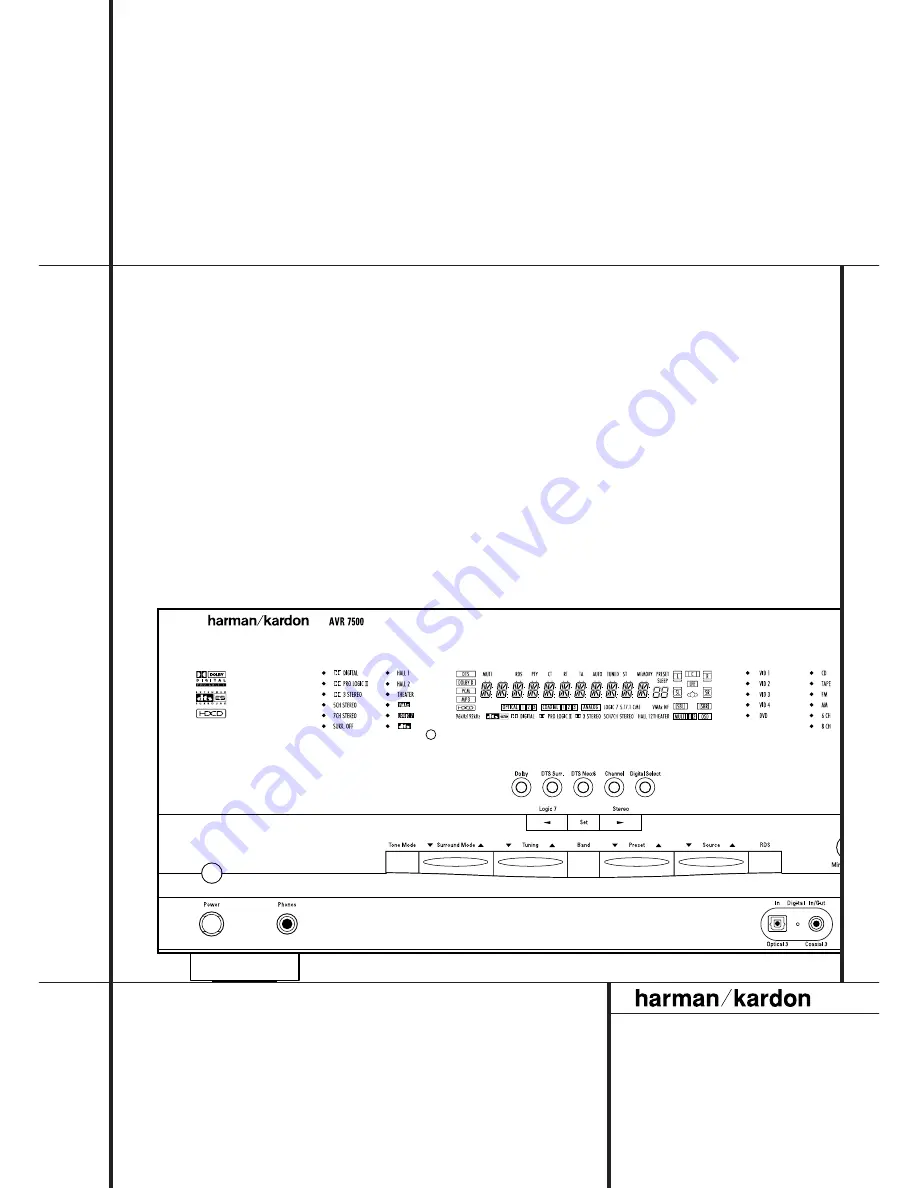
Страница 5: ...order Note that DOLBY DIGITAL mode is available only with digital input selected and the other modes only when a Dolby Digital source is not playing 6 DTS Surround Mode Selector When a DTS source is i...
Страница 6: ...elector button cycles the AVR through the vari ous DTS Neo 6 modes which extract a five or seven channel surround field from two channel program material from PCM source or analog input signal The fir...
Страница 7: ...formation Pro Logic flag on is detected For more information see page 34 If you desire 5 1 channel audio check the audio settings in the menus for your DVD disc to make sure that a 5 1 channel Dolby D...
Страница 8: ...page 40 for more information on tuner presets T Sleep Indicator This indicator lights when the Sleep function is in use The numbers in the Preset Number Sleep Timer R indicators will show the minutes...
Страница 9: ...to the AM and GND terminals in accordance with the instructions supplied with the antenna FM Antenna Connect the supplied indoor or an optional external FM antenna to this terminal Tape Inputs Connec...
Страница 10: ...esponding color RGB connection is not possible if the source out puts a separate sync signal see page 16 Remote IR Output This connection permits the IR sensor in the receiver to serve other remote co...
Страница 11: ...Direct Button Tuning Up Down OSD Button Dolby Mode Select Button DTS Digital Mode Selector Logic 7 Mode Select Button Transport Controls Light Button Skip Up Down Buttons Stereo Mode Select Button DTS...
Страница 12: ...ach press of the button changes the time until turn off in the following order Hold the button pressed for two seconds to turn off the Sleep mode setting Note that this button is also used to change c...
Страница 13: ...more information on storing and recalling macros RDS Select Button Press this button to dis play the various messages that are part of the RDS data system of the AVR 7500 s tuner See page 41 for more...
Страница 14: ...ng one of these buttons will change the input Tuning Up Down Fast Play These but tons may be used to change the frequency of the tuner These buttons may also control the Fast Play or Fast Reverse func...
Страница 15: ...to the speakers be cer tain to observe proper polarity Note that the positive terminal of each speaker connection now carries a specific color code as noted on page 9 However most speakers will still...
Страница 16: ...CR connect the Out plugs to the Out jacks on the AVR Note that with some adapter types it may be just turned around If no signal is audi ble visible when the VCR is playing connect the Out plugs to th...
Страница 17: ...able specific control sig nals apart from Audio Video signals will be fed to the TV These specific signals are With all video sources the signal for automatic input selection that switches the TV auto...
Страница 18: ...nnect the Multiroom Output jacks on the rear panel of the AVR to the audio input of the remote room amplifier Use the appropriate speaker wire to connect the optional power amplifier to the remote spe...
Страница 19: ...of the room sound smooth When the AVR 7500 is used in 5 1 channel oper ation the preferred location for surround speak ers is on the side walls of the room at or slightly behind the listening positio...
Страница 20: ...e be used This will place a com plete status report or option listing on the screen making it easier to view the available options and make the settings on the screen The Semi OSD mode uses one line d...
Страница 21: ...he front panel analog Video 4 Jacks are nor mally set as an input for use with camcorders video games and other portable audio video products but they may be switched to an output for connection to po...
Страница 22: ...er speaker is used Note that when the Logic 7 Cinema or Enhanced surround modes are selected a Center speaker must be used the Logic 7 Music mode works well without a Center too 5 When you have comple...
Страница 23: ...F and then the buttons D on the remote until the correct speaker set ting is shown and press the Set button F again to confirm the selection To assist in making these settings the icons in the Speaker...
Страница 24: ...ully enveloping multichannel surround from either two channel Stereo or Matrix encoded programming such as VHS cas settes laserdiscs or television broadcasts pro duced with Dolby surround In the 5 1 c...
Страница 25: ...ings for the Dolby Digital mode this will include the Center delay setting and the sur round delay for the Pro Logic mode will be set automatically press the Set F button and select any input now that...
Страница 26: ...if it is in use 2 Adjust the volume so that it is at 15 as shown in the on screen display or Main Information Display Y 3 Select any input associated with the surround mode for which you want to adju...
Страница 27: ...ume must be lowered after the adjustment for all channels is made but BEFORE you return to the main menu and the test tone turns off NOTE Remember to verify that the speakers have been properly connec...
Страница 28: ...com pensate level differences between speakers that may be different with each surround mode or to increase or decrease the level of certain speakers intentionally depending on the surround mode sele...
Страница 29: ...from either surround encoded programs or conventional stereo Logic 7 Enhance material Depending on the number of speakers in use and the selection made in the SURROUND SELECT menu the 5 1 versions of...
Страница 30: ...he Headphones Output 4 When headphones are being used the Far Field mode will push the sound field away from your ears reducing the inside the head sensation often experienced when using headphones 5...
Страница 31: ...uts As the input is changed the AVR 7500 will automatically switch to the digital input if selected surround mode and speaker configura tion that were entered during the configuration process for that...
Страница 32: ...rs you should select Harman s patented VMAx mode delivering a virtu ally three dimensional sound space with two speakers only Surround modes are selected using either the front panel controls or the r...
Страница 33: ...7500 will automatically sense that it is an HDCD recording and the HDCD indicator A will illu minate on the front panel to remind you that an HDCD disc is playing It is important to note that the HDC...
Страница 34: ...ings When a PCM bitstream is present all modes except Dolby Digital and DTS are available When this indicator lights the CD that is playing is encoded using the special High Definition Compatible Dig...
Страница 35: ...onnected to the outputs for Tape Outputs or Video 1 or 2 Outputs in the record mode When a digital audio recorder is connected to any of the Digital Audio Outputs you are able to record the digital si...
Страница 36: ...When your test source is a normal disc with music signals you may adjust the level for each channel and surround mode as you prefer e g you may lower the center channel level when you find it to be to...
Страница 37: ...rned off Turn On Volume Level As is the case with most audio video receivers when the AVR 7500 is turned on it will always return to the volume setting in effect when the unit was turned off However y...
Страница 38: ...in this menu this is a permanent setting change and the time out entry will remain in effect until it is changed even when the unit is turned off If you wish to make other adjustments in the menu pre...
Страница 39: ...tor 5 to turn the unit on to the last source or any of the other Selector buttons to turn on to a specific source As long as an IR feed to the AVR 7500 has been established from the remote room using...
Страница 40: ...a time or press and hold it to locate a specific station When the TUNED indicator W illuminates the station is properly tuned and should be heard with clarity 5 Stations may also be tuned directly by...
Страница 41: ...l show a NO TYPE NO TEXTor NO TIME message after the individual time out In any FM mode the RDS function requires a strong enough signal for proper operation If you receive a partial message or any of...
Страница 42: ...in mind that many manufacturers use a number of different combinations of codes so it is a good idea to make certain that not only does the Power control work but that the volume channel and transpor...
Страница 43: ...ons on the remote The buttons with the following numbers are not learnable for numbers see drawing on page 11 4 7 8 B I O Q In these cases the Program SPL Indicator 2 keeps flashing after the button w...
Страница 44: ...hile entering commands for Power On of any device during a macro sequence press the Mute button DO NOT press the Power ON button 3 Remember to press the appropriate Input Selector button 4 before func...
Страница 45: ...and product type used the functions listed in the Function List tables may not correspond with the function the unit reacts on the command In these cases it s a good idea to edit the reaction of the u...
Страница 46: ...lector button 4 for the device that will be used to change the channels The Program SPL Indicator 2 will blink green three times and then go out to confirm the data entry Example To control the transp...
Страница 47: ...et all commands or codes that you have entered will be erased and will need to be re entered 1 Press any of the Input Selector buttons 4 and the O button H at the same time until the Program SPL Indic...
Страница 48: ...ose 30 Move Adjust Down Down 31 Delay Prev Ch Delay Adjust Return Open Close 32 1 1 1 1 33 2 2 2 2 34 3 3 3 3 35 4 4 4 4 36 5 5 5 5 37 6 6 6 6 38 7 7 7 7 39 8 8 8 8 40 Tun M Tuner Mode Chapter Repeat...
Страница 49: ...Up Up 25 Speaker Menu Menu Menu Menu Menu 26 Left Left Left Left 27 Set Enter Enter Enter Enter 28 Right Right Right Right 29 Digital Exit Exit Exit Exit Exit 30 Down Down Down Down 31 Delay Prev Ch P...
Страница 50: ...nto a live outlet Check to see if outlet is switch controlled Display lights but no sound Intermittent input connections Make certain that all input and speaker or picture connections are secure Mute...
Страница 51: ...at PAL NTSC Input Level Impedance 1Vp p 75 ohms Output Level Impedance 1Vp p 75 ohms Video Frequency Response Composite and S Video 10Hz 8MHz 3dB Video Frequency Response Component 10Hz 35MHz 3dB Gene...
Страница 52: ...250 Crossways Park Drive Woodbury New York 11797 www harmankardon com Harman Consumer International 2 route de Tours 72500 Ch teau du Loir France 2001 Harman Kardon Incorporated Part No 5527 3100...