background image

SYSTEM CONFIGURATION

17

System Configuration

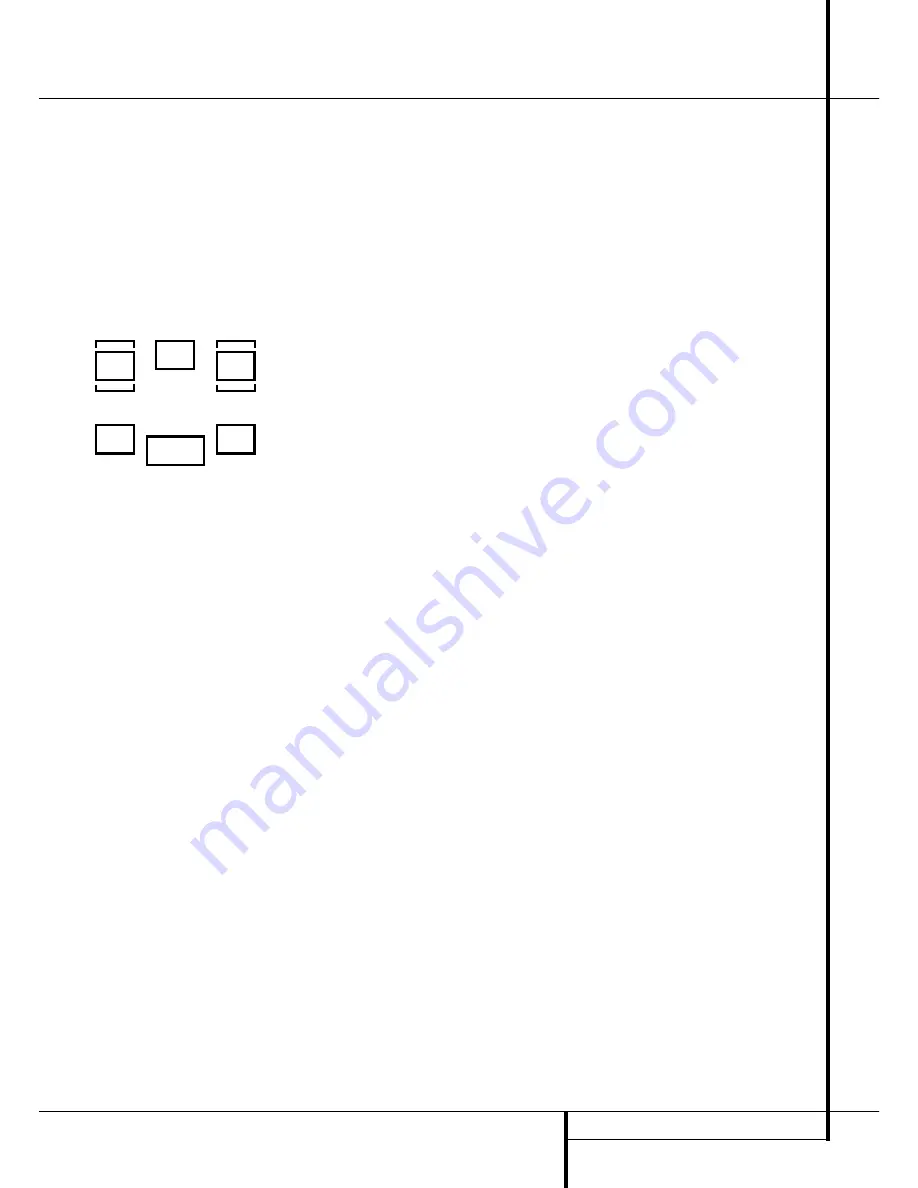
To assist in making these settings, the icons in
the 

Speaker/Channel Input Indicators

¯

will change as the speaker type is selected at
each position. When only the inner icon box is lit,
the speaker is set for “small.” When the inner box
and the two outer boxes with circles inside them
are lit, the speaker is set for “large." When no
indicator appears at a speaker location, that
position is set for “none” or “no” speaker.

As an example, in the Figure below, the left front
and right front speakers are set for “large,” the
center, left surround and right surround speakers
are set for small, and a subwoofer is set.

Triple Crossover Setting

The AVR 505 Limited Edition is unique among all
receivers in its price class to provide Triple Cross-
over functionality. Where conventional bass man-
agement systems only accommodate a global
crossover setting, Harman Kardon’s Triple Cross-
over system allows you to set a different cross-
over point for the front left/right, center and sur-
round speakers. This is key to creating a seamless
soundfield when a system uses different brands
or models of speakers from one of these three
groupings to another.

If you are not familiar with what the crossover
point is, the term refers to the frequency at which
the full-range signal is divided between your
main speakers and the subwoofer. Since the sub-
woofer is specially designed for low frequency
reproduction, it isn’t able to reproduce high fre-
quencies. Conversely, by relieving the main
speakers of the requirement to reproduce bass
frequencies, it is possible to build smaller, more
efficient “satellite” style speakers. Setting the
crossover frequency properly means that each
speaker does the job it was intended to do, with-
out the strain or possible damage caused by
being fed the wrong signals. In order to properly
take advantage of the Triple Crossover function
we encourage you to consult the owner’s manual
for your speakers to determine what the lowest
frequency is that they are designed for, That is
the number that will be used in making the set-
tings in this section.

Note that the factory default setting is a cross-
over point of 100Hz for all speakers. If your
speakers have a crossover at that setting you do
not need to make any of these adjustments and
you should proceed to the next step. However, if,
for example, your front speakers have a crossover

point of 80Hz, your center speaker crosses over
at 120Hz and your surround speakers crossover
at yet a different point, adjusting these settings
will help establish the proper relationship
between the low frequency sound that is sent to
your subwoofer and the balance of the sound
that is reproduced by your main speakers.

If your speaker complement does require a
change to the crossover settings, proceed as fol-
lows:
1. Press the 

Speaker Button

Ù

.

2. Press the 

/

¤

Buttons

C

the remote or

the 

/

Buttons

5

on the front panel so that

SPEAKER XOVER

appears in the 

Main

Information Display

Ú

and press the 

Set

Button

E

Ó

to enter the crossover menu

tree.

3. When 

FRONT 3X-FREQ

appears in the

Main Information Display

Ú

, press the 

Set

Button

E

Ó

to change the setting for the

front left/right speakers.

4. Press the 

/

¤

Buttons

C

on the remote or

the 

/

Buttons

5

on the front panel, to scroll

through the available choices, and when the
crossover frequency that matches your speakers
is appears in the 

Main Information Display

Ú

, press the 

Set Button

E

Ó

to return to

the speaker group selection.

5. Press the 

/

¤

Buttons

C

on the remote or

the 

/

Buttons

5

on the front panel again to

select another speaker group, either 

CENTER

FREQ

to adjust the crossover for the center

channel speaker, or 

SURR 3X-FREQ

to

adjust the crossover for the surround speakers,
and press the 

Set Button

E

Ó

when the

desired speaker group appears to change the
setting as needed, following the instructions in
step 4, above.

6. When all required crossover settings have
been entered, press the 

Set Button

E

Ó

to

return to normal operation.

Global/Independent Bass Manager
Memory

A feature that is unique to the AVR in its class is
the ability to allow the storage of different
speaker size settings for each input source. In
most cases you will not need to take advantage
of this capability, particularly when the speakers
used are all frequency-limited “satellite” type
models. However, when a system’s front speakers
are large, full-range models, you may wish to use
different “large” or “small” settings for inputs
such as the tuner or CD, where two-channel
stereo music may be the desired listening mode,
as opposed to the DVD or other video-related
inputs where a subwoofer will be used.

If you do not need to create different speaker
configuration settings for each input, skip to the
next section.

To take advantage of this capability, follow these
steps:

1. Configure the speaker size information as indi-
cated on page 15/16. This sets the common
baseline for all inputs.

2. Select the input that you wish to have differ-
ent settings than the original ones by pressing
the appropriate 

Input Selector

4

.

3. Press the 

Speaker Button

Ù

and then

press the 

/

¤

Buttons

C

on the remote or

the 

/

Buttons

5

on the front panel so that

BASS MANAGER

appears in the 

Main

Information Display

Ú

. Press the 

Set

Button

E

Ó

.

4. When 

GLOBAL

appears in the 

Main

Information Display

Ú

press the 

/

¤

Buttons

C

on the remote or the 

/

Buttons

5

on the front panel to select 

INDEPEN-

DENT

. Press the 

Set Button

E

Ó

to enter

the request to the AVR’s memory.

5. Once the 

BASS MANAGER

message

reappears in the 

Main Information Display

Ú

you have configured the AVR so that different

speaker size and crossover settings may be cho-
sen for each input. To enter these settings, first
wait five seconds until the unit returns to normal
operation. At that time, select another input and
repeat the instruction steps for Speaker Setup
and Triple Crossover Setting as shown on the
previous pages.

Surround Setup

Once the speaker setup has been completed, the
next setup step is to set the surround mode you
wish to use with each input. Since surround
modes are a matter of personal taste, feel free to
select any mode you wish – you may change it
later. The Surround Mode chart on page 24 may
help you select the mode best suited to the input
source selected. However, to make it easier to
establish the initial parameters for the AVR, it is
best to leave the default setting of Logic 7 Music
mode for most analog inputs and Dolby Digital
for inputs connected to digital sources. In the
case of inputs such as a CD Player, Tape Deck or
Tuner, you may wish to set the mode to Stereo, if
that is your preferred listening mode for standard
stereo sources, where it is unlikely that surround
encoded material will be used.

To set the surround mode you wish to use with
the input selected, press the 

Surround Mode

Selector

button 

7

on the front or 

9

and the

/

¤

buttons 

C

on the remote until the

desired surround mode´s name appears in the

Main Information Display

Ú

.

As the modes are changed, a blue LED will also
light next to the mode names in the 

Surround

Mode Indicators

$

on the front panel.

L

R

C

SL

SR

LFE

Содержание AVR 505 LIMITED EDITION

Страница 1: ...Limited Edition Audio VideoReceiver OWNER S MANUAL DIGITAL LOGIC 7 VID 1 DVD CD FMAM TAPE 6 CH VID 2 VID 3 PRO LOGIC 3 STEREO DSP 5 CH STEREO SURR OFF Surr Select Coaxial RDS Power for the Digital Rev...

Страница 2: ...r Operation 26 RDS Operation 27 Programming the Remote 27 Programming the Remote with Codes 28 Programmed Device Function 28 Macro Programming 29 Volume Punch Through 29 Channel Control Punch Through...

Страница 3: ...s are available In addition to providing a wide range of listening options the AVR 505 Limited Edition is easy to configure so that it provides the best results with your speakers and specific listeni...

Страница 4: ...ain that proper space is provided both above and below the unit for ventilation If this product will be installed in a cabinet or other enclosed area make certain that there is sufficient air movement...

Страница 5: ...ttons When you are establish ing theAVR s configuration settings use these buttons to select from the choices available as shown in the Main Information Display 6 Tone Mode Pressing this button enable...

Страница 6: ...t right chan nels by as much as 10dB Set this control to a suitable position for your taste or room acoustics Volume Control Turn this knob clockwise to increase the volume counterclockwise to decreas...

Страница 7: ...ed make connections to the AM and GND terminals in accordance with the instructions supplied with the antenna Video 1 Audio Outputs Connect these jacks to the RECORD INPUT audio jacks on a VCR or any...

Страница 8: ...ice The power will remain on at this outlet regardless of whether the AVR is on or off in Standby pro vided that the Main Power switch 1 is on Note The total power consumption of all devices connected...

Страница 9: ...s Transport Controls Skip Up Down Buttons RDS Select Button Preset Up Down Clear Button Memory Button Delay Prev Ch Button Speaker Select Spare Button Volume Up Down TV Video Selector Mute Dim Button...

Страница 10: ...ation Note that this button is also used to tune channels when the TV VCR and SAT receiver is selected using the Input Selector 4 A Night Mode Press this button to activate the Night mode This mode is...

Страница 11: ...utton is pressed with the Input Selector button 4 to begin the programming process See page 27 for more information on programming the remote NOTE As any of the remote buttons pressed is active with t...

Страница 12: ...n area of 1 5 mm2 may be used for short runs of less than 4 m We do not recom mend that you use cables with an area less than 1mm2 due to the power loss and degradation in performance that will occur...

Страница 13: ...a VCR connect the Out plugs to the Out jacks on the AVR Note that with some adapter types it may be just turned around If no signal is audible visible when the VCR is playing connect the Out plugs to...

Страница 14: ...not shielded even with complete surround sets only the Center speaker may be Depending on the specifics of your room acoustics and the type of speakers in use you may find that imaging is improved by...

Страница 15: ...log source except for the DVD input which has the Coaxial Digital Input 1 as the default with Logic 7 Music as the surround mode all speaker positions set to small and a subwoofer connected Before us...

Страница 16: ...Set button E again and then use the buttons C on the remote or the Selector buttons 5 on the front panel to select the option that best describes your system based on the Surround speaker definitions...

Страница 17: ...to the speaker group selection 5 Press the Buttons C on the remote or the Buttons 5 on the front panel again to select another speaker group either CENTER FREQ to adjust the crossover for the center c...

Страница 18: ...st the delay time setting Note that the delay time is not adjustable for any other modes Due to the different distances between the listening position for the front channel speakers and the surround s...

Страница 19: ...ers have been properly connected As the test noise circulates listen to make certain that the sound comes from the speaker position shown in the Main Information Display If the sound from a speaker lo...

Страница 20: ...anel Video 3 Inputs may be used to connect a device such as a video game or camcorder to your home entertainment system on a temporary basis As the input source is changed the new input name will appe...

Страница 21: ...n s patented VMAx mode No surround channels VMAx Far delivers a three dimensional sound space with the illusion of phantom speakers at the center and surround positions The VMAx N or Near Field mode s...

Страница 22: ...in use In addition when a digital source is present the AVR will automatically select and switch to the correct mode Dolby Digital or DTS regardless of the mode that has been previously selected For...

Страница 23: ...the number of channels present in the data An example of this type of display is 3 2 1 The first number indicates how many discrete front channel signals are present A 3 tells you that separate front...

Страница 24: ...ed and adjust to accommodate it 4 When a Dolby Digital or DTS source is playing you normally may not be able to select some of the analog surround modes such as Dolby Pro Logic II Dolby 3 Stereo Hall...

Страница 25: ...time all information must be reentered Tuner Operation The AVR s tuner is capable of tuning AM FM and FM Stereo broadcast stations and receiving RDS data Stations may be tuned manually or they may be...

Страница 26: ...quires a strong enough signal for proper operation Program Search PTY An important feature of RDS is its capability of encoding broadcasts with Program Type PTY codes that indicate the type of materia...

Страница 27: ...se a number of different combinations of codes so it is a good idea to make certain that not only does the Power control work but that the volume channel and transport controls work as they should If...

Страница 28: ...erate check to see if another code set will work with more buttons Depending on the brand and product type used the functions listed in the Function List tables may not correspond with the function th...

Страница 29: ...s the VID 1 VCR Input Selector button 4 and the Mute button at the same time Next release them and press the Volume Down button followed by the VID 2 TV Input Selector button 4 NOTE To remove the Chan...

Страница 30: ...ust Menu Intro 25 Left 26 Set Set Enter 27 Right 28 Digital Exit Digital Input Select Open Close 29 Move Adjust Down Down 30 Delay Prev Ch Delay Adjust Return Open Close 31 1 1 1 1 32 2 2 2 2 33 3 3 3...

Страница 31: ...u Menu Menu 25 Left Left Left Left 26 Set Enter Enter Enter Enter 27 Right Right Right Right 28 Digital Exit Exit Exit Exit Exit 29 Down Down Down Down 30 Delay Prev Ch Prev Channel Prev Channel Prev...

Страница 32: ...1 is pushed into a live outlet Check to see if outlet is switch controlled Display lights but no sound Intermittent input connections Make certain that all input and speaker or picture connections are...

Страница 33: ...nal to Noise Ratio 45dB Usable Sensitivity Loop 500 V Distortion 1kHz 50 Mod 0 8 Selectivity 10kHz 30dB Video Section Video Format PAL NTSC Input Level Impedance 1Vp p 75 ohms Output Level Impedance 1...

Страница 34: ...250 Crossways Park Drive Woodbury New York 11797 www harmankardon com Harman Consumer International 2 route de Tours 72500 Ch teau du Loir France 08 2003 Harman Kardon Incorporated Part No CQE1A8654...

Отзывы: