background image

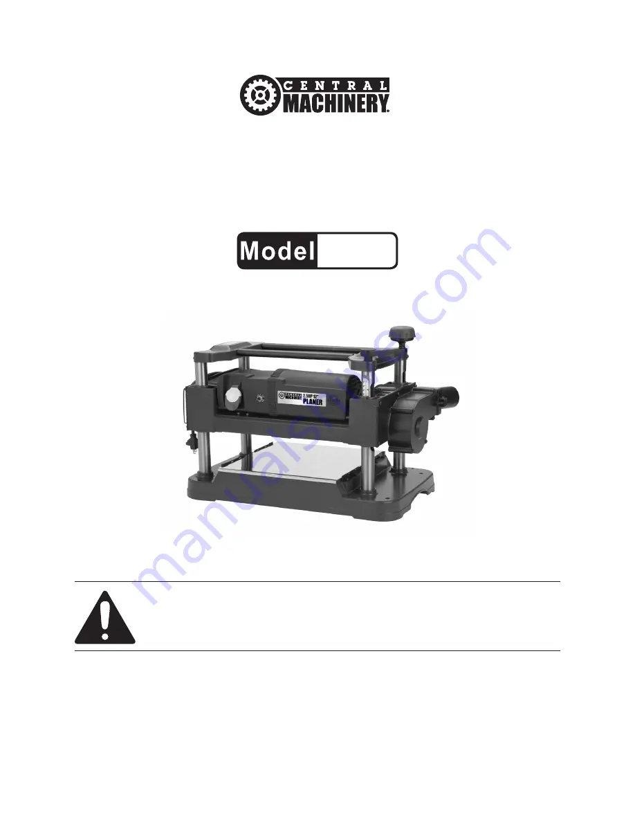
2-1/2 HP / 12” PLANER  

95082

SEt uP ANd OPERAtiNg iNStRuctiONS

Visit our website at: http://www.harborfreight.com

 Read this material before using this product. 

Failure to do so can result in serious injury. 

SAVE tHiS mANuAL.

Copyright

©

 2010 by Harbor Freight Tools

®

.  All rights reserved.  No portion of this manual or any artwork 

contained  herein  may  be  reproduced  in  any  shape  or  form  without  the  express  written  consent  of 

Harbor Freight Tools.  Diagrams within this manual may not be drawn proportionally.  Due to continuing 

improvements,  actual  product  may  differ  slightly  from  the  product  described  herein.   Tools  required  for 

assembly and service may not be included.

For technical questions or replacement parts, please call 1-800-444-3353.

Revised 11h

Содержание 95082

Страница 1: ...eserved No portion of this manual or any artwork contained herein may be reproduced in any shape or form without the express written consent of Harbor Freight Tools Diagrams within this manual may not be drawn proportionally Due to continuing improvements actual product may differ slightly from the product described herein Tools required for assembly and service may not be included For technical q...

Страница 2: ...f not avoided could result in death or serious injury CAUTION used with the safety alert symbol indicates a hazardous situation which if not avoided could result in minor or moderate injury NOTICE is used to address practices not related to personal injury CAUTION without the safety alert symbol is used to address practices not related to personal injury General Power Tool Safety Warnings WARNING ...

Страница 3: ...nse when operating a power tool Do not use a power tool while you are tired or under the influence of drugs alcohol or medication A moment of inattention while operating power tools may result in serious personal injury Use personal protective b equipment Always wear ANSI approved eye protection Safety equipment such as dust mask non skid safety shoes hard hat or hearing protection used for approp...

Страница 4: ...ls Check e for misalignment or binding of moving parts breakage of parts and any other condition that may affect the power tool s operation If damaged have the power tool repaired before use Many accidents are caused by poorly maintained power tools Keep cutting tools sharp and f clean Properly maintained cutting tools with sharp cutting edges are less likely to bind and are easier to control Use ...

Страница 5: ...aker could cause pacemaker interference or pacemaker failure In addition people with pacemakers should Avoid operating alone Do not use with power switch locked on Properly maintain and inspect to avoid electrical shock Any power cord must be properly grounded Ground Fault Circuit Interrupter GFCI should also be implemented it prevents sustained electrical shock Some dust created by power 14 sandi...

Страница 6: ...trically malfunction or break down grounding provides a low resistance path to carry electricity away from the user reducing the risk of electric shock See 3 Prong Plug and Outlet The grounding prong in the plug is 2 connected through the green wire inside the cord to the grounding system in the tool The green wire in the cord must be the only wire connected to the tool s grounding system and must...

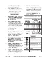
Страница 7: ...e required See Table A If you are using one extension cord 5 for more than one tool add the nameplate amperes and use the sum to determine the required minimum cord size See Table A If you are using an extension cord 6 outdoors make sure it is marked with the suffix W A W in Canada to indicate it is acceptable for outdoor use Make sure the extension cord is 7 properly wired and in good electrical ...

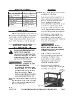
Страница 8: ...ng any adjustments to the tool Note For additional information regarding the parts listed in the following pages refer to the Assembly Diagram near the end of this manual Assembly NOTE This should always be mounted to a workbench before use Select an area with enough room to 1 fit the chosen dust collection system Select a workbench to mount the Planer Place the Planer on a workbench able to suppo...

Страница 9: ... AND BREAK EXHAUST FAN FOR BEST RESULTS USE VACUUM SYSTEM INSTEAD OF DUST BAG WARNING 9 Make sure Blade is fastened and tightened down securely before beginning any work Refer to Changing Cutting Blades section of this manual to tighten blade properly Operating Instructions Read the entire Important Safety Information section at the beginning of this manual including all text under subheadings the...

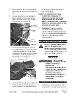
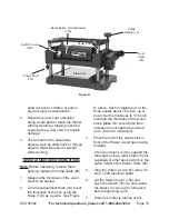
Страница 10: ... 103 as a guide See Figure D above Each complete turn of the Knob equals about 1 16 inch up or down Set the thickness to 1 16 inch less than the thickness of the wood stock Make thin cuts at first then increase the cut depth as required up to 3 32 inch maximum Place the end of the wood stock in 3 front of the Planer wood grain facing forward If the wood stock is long support the full length using ...

Страница 11: ...han a single deep cut Note Always keep the boards being planed level Support long boards at both ends 11 Plane along the grain of the wood 12 Plane alternating sides of the board until the desired thickness is achieved 13 When planing multiple boards to same thickness place ends so they are touching butting for best results 14 An assistant can return the boards to the operator using the Rollers 13...

Страница 12: ...um grease Carbon Brush Maintenance 4 The carbon brushes may require maintenance when motor performance of tool decreases or stops working completely To maintain brushes Remove the brush caps on the front a and back of the motor housing Remove the carbon brushes b from the housing Keep track of which orientation the old carbon brushes were in to prevent needless wear if they will be reinstalled If ...

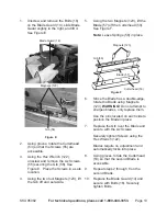
Страница 13: ... the Cutterhead 53 See Figure F Note Leave Springs 58 in place Figure F 6 Since the Blade has a double edge rotate the Blade using Magnets 123 WARNING Do not attempt to sharpen blades only replace them Use the pins located on each side to position the Blade in place 7 Replace the Gib over the Blade and secure with the six Screws Securely tighten Screws using the Hex Wrench 122 Blades require no ad...

Страница 14: ...ing 4 Remove the V Belt 65 from the Pulley 64 and replace with new 135J6 V belt Contact Harbor Freight Tool for replacement belts 26 Reassemble the Planer WARNING If the supply cord of this power tool is damaged it must be replaced only by a qualified service technician PLEASE READ THE FOLLOWING CAREFULLY The manufacturer and or distributor has provided the parts list and assembly diagram in this ...

Страница 15: ...ws worn 3 Friction between roller case and 4 covers Roller case not parallel 5 Clean and lubricate sprockets and chain 1 Clean and lubricate screws and columns 2 Replace screws 3 Clean and lubricate roller case and cover 4 Adjust roller case 5 Board feeds in but will not move through Out feed rollers are clogged 1 Too much pressure on cutter head 2 from long board Clean Planer 1 Use supports to ho...

Страница 16: ...8x8mm Set Screw 1 45 M5x0 8x10mm Pan Head Screw 1 46 Cable Clamp 1 47 Roller Case 1 48 M5x0 8x10mm Socket Head Bolt 2 Part Description Q ty 49 Belt Guard 1 50 M5x0 8x12mm Socket Head Bolt 8 51 Flat Washer M8 1 52 M8x1 25x20mm Hex Head Bolt 1 53 Cutterhead 1 54 Pin 4 55 M6x1 0x16mm Pan Head Screw 12 56 Gib 2 57 Blade set of 2 2 58 Spring 4 59 M5x5x10mm Key 1 60 Motor Pulley 1 61 6203ZZ Ball Bearing...

Страница 17: ...her M4 4 150 Motor Assembly includes key nos 1 29 1 Part Description Q ty 151 M5x0 8x20mm Pan Head Screw 3 152 Lock Washer M5 3 153 Housing Left 1 154 Gasket 1 155 Circuit Breaker 1 156 Strain Relief Bushing 1 157 Line Cord 1 158 Wire Connector 1 159 M4 8x2 1x16mm Self threading Screw 1 160 Switch 1 161 Switch Frame 1 162 Switch Cover 1 164 M4 8x2 1x20mm Self threading Screw 3 165 Lock Washer M5 3...

Страница 18: ...SKU 95082 For technical questions please call 1 800 444 3353 Page 18 ASSEMBLY DIAGRAM ...

Страница 19: ...SKU 95082 For technical questions please call 1 800 444 3353 Page 19 ASSEMBLY DIAGRAM continueD ...

Страница 20: ...SKU 95082 For technical questions please call 1 800 444 3353 Page 20 ASSEMBLY DIAGRAM continueD ...

Страница 21: ...sequential damages arising from the use of our product Some states do not allow the exclusion or limitation of incidental or consequential damages so the above limitation of exclusion may not apply to you This warranty is expressly in lieu of all other warranties express or implied including the warranties of merchantability and fitness To take advantage of this warranty the product or part must b...

Отзывы: