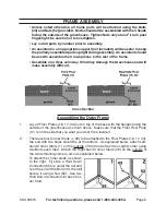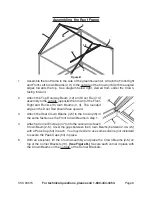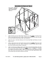
background image

Page 7

SKU 94515

for technical questions, please call 1-800-444-3353.

3. 

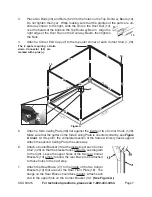
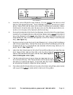
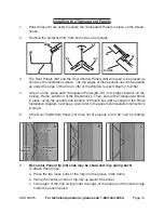
Place two Bolts (43) and Nuts (52) into the holes on the Top Doorway Beam (12).  
Do not tighten them yet.  While making sure that the profiles of the parts are ori-
ented as shown to the right, slide the slot on the Door Rail (14) 
over the heads of the bolts on the Top Doorway Beam.   Align the 
right edge of the Door Rail on the Doorway Beam, then tighten 
the Nuts.
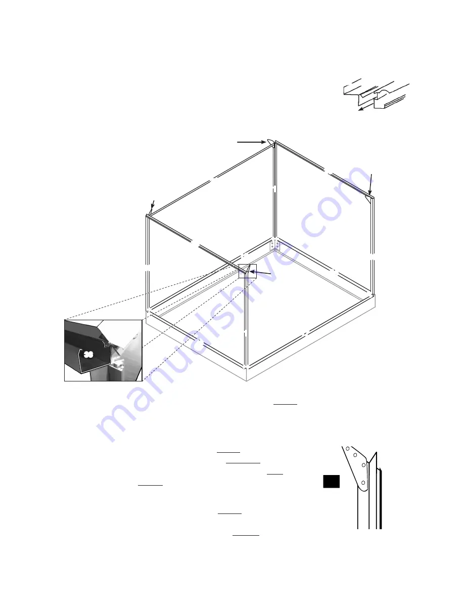
Attach a Corner End Cap (47) to the top outer corner of each Corner Stud (1, 29).

4. 

(fr

ont)

(Rear)

(Right)

figure A

36

(left)

the  8  spots  requiring  a  Hold-
down  connector  (55)  are 
marked with a plus (+).

16

34

34

1

29

1

29

36

36

13

13

13

17

13

21

+

+

++

+

+

+

+

5. 

Attach a Side Ceiling Plate (36) flat against the inside of two Corner Studs (1,29).  
Make sure that the gutter on the Side Ceiling Plate is oriented correctly, see 

figure 

inset.  At this point, the completed section of the frame will likely need support.  
Attach the second Ceiling Plate the same way.
Attach a Corner Bracket (13) at the 

6. 

inside top of each Corner 

Stud (1,29) so that the bracket faces upwards, see diagram 
to the right.  Leave the upper holes of the two rear Corner 
Brackets (13) empty to allow the rear brace to be attached 
to those holes in the next step.

Attach the Rear Brace (21) to the 

7. 

inside of the two Corner 

Brackets (13) that are over the Rear Floor Plate (16).  The 
flange on the Rear Brace should face inward.  Attach each 
end to the upper hole on the Corner Bracket (13).  

(See figure A.)

14

12

Содержание 94515

Страница 1: ...ortion of this manual or any artwork contained herein may be reproduced in any shape or form without the express written consent of Harbor Freight Tools Diagrams within this manual may not be drawn pr...

Страница 2: ...9 Assembling the Roof Studs and Braces 11 Assembling the Windows 12 Assembling the Door 12 Installing the Transparent Panels 14 Panel Installation Diagram 15 INSPECTION MAINTENANCE AND CLEANING 16 PA...

Страница 3: ...his product Although this greenhouse does include some protective covers there are still some exposed sharp edges In addition protective covers may fall off in time Children must be supervised if allo...

Страница 4: ...ere is adequate surrounding workspace Avoid high traffic areas Always keep the work area free of obstructions grease oil trash and other debris PROPER GREENHOUSE LOCATION 13 Make sure the Greenhouse i...

Страница 5: ...that is sheltered from the wind The door of the greenhouse should not open towards the prevailing wind if possible Excavate an area for the base of the greenhouse The area must be 4 6 wide by 1 6 5 lo...

Страница 6: ...se 57 Gravel Rear Side Floor Plates 16 34 ground outside greenhouse Base 57 58 Gravel Cross Section Assembling the Outer Frame Lay all Floor Plates 16 17 34 out on top of the base with the flanges fac...

Страница 7: ...36 13 13 13 17 13 21 5 Attach a Side Ceiling Plate 36 flat against the inside of two Corner Studs 1 29 Make sure that the gutter on the Side Ceiling Plate is oriented correctly see Figure A inset At t...

Страница 8: ...wn of the Front Right and Front Left Crown Beams 2 3 The rounded edge on the Door Rail should face upward Attach the Rear Crown Beams 4 5 to the Crown 35 in 3 the same fashion as the Front Crown Beams...

Страница 9: ...tach the tops of the Rear Studs 8 9 to the Rear Right and Rear Left Crown 2 Beams 4 5 Attach a Side Stud 10 in the center of each side to the 3 outside of the frame with an extra Bolt 43 in the slot S...

Страница 10: ...the Front Diagonal Braces 25 to the Bolt left exposed on the Floor Plate 17 from the last step See Figure C Remove next bolt up from the front Corner Brackets 13 Connect the Front Braces 7 23 to the e...

Страница 11: ...Ceiling Plates 36 using another Bolt 43 Slide a Left Window Support Beam 15a onto two Roof Studs 11 on the left side 2 of the greenhouse with the predrilled holes on the underside and the flat side fa...

Страница 12: ...at 6 the top of the Crown 35 see illustration to the right The win dow should be aligned with the Window Brace 51 underneath it Slide the window into place over the Window Support Beam 15a 15b Gradua...

Страница 13: ...led the correct way with the gap facing the back of the door see diagram to the right Attach the Bottom Door Frame 27 to the Left Right Door Frames 20 28 using two Screws 44 on each side the one on th...

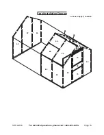
Страница 14: ...l 62 70 in its proper location on the 4 Ceiling Frame and Door of the Greenhouse Then secure the Transparent Panel in place using the quantity and location of Panel Clips 46 as shown in the Panel Inst...

Страница 15: ...Page 15 SKU 94515 For technical questions please call 1 800 444 3353 Panel Installation Diagram Panel Clip 67 Location 62 62 63 63 64 64 64 64 65 65 66 66 67 68 70 70 69...

Страница 16: ...Greenhouse in a box and in a clean dry location PLEASE READ THE FOLLOWING CAREFULLY THE MANUFACTURER AND OR DISTRIBUTOR HAS PROVIDED THE PARTS DIAGRAM IN THIS MANUAL AS A REFERENCETOOL ONLY NEITHERTH...

Страница 17: ...1 13 Corner Bracket 4 14 Door Rail 4 2 1 15a Left Window Support Beam 2 1 1 15b Right Window Support Beam 2 1 1 16 Rear Floor Plate 6 1 17 Front Floor Plate 6 1 18 Window Stop 2 Part Description Q ty...

Страница 18: ...il End Cap 1 50 Left Rail End Cap 1 51 Window Brace 2 52 Nut M6 89 53 Door Roller 2 54 Peak Cap 2 Part Description Q ty 55 Hold down Connector 16 56 Hex Wrench 1 57 Front Rear Base Plate 2 58 Side Bas...

Отзывы: