background image

SAFETY INFORMATION

4

WARNING


To reduce the risk of fire, electrical shock or personal injury, mount fan to outlet box                   

            marked "ACCEPTABLE FOR FAN SUPPORT OF 35 LBS. OR LESS" and use 
            mounting screws provided with the outlet box. Most outlet boxes commonly used for the 
support of lighting fixtures are not acceptable for fan support and may need to be replaced. 
Consult a qualified electrician if in doubt. 

When mounting fan to a ceiling outlet box, use a METAL octagonal outlet box; do NOT use a 
plastic outlet box. Secure the outlet box directly to the building structure. The outlet box and its 
support must be able to support the moving weight of the fan (at least 35 lbs.). 


 To avoid personal injury, the use of gloves may be necessary while handling fan parts with


 sharp edges.

To reduce the risk of fire, electrical shock or personal injury, wire connectors provided with this fan 
are designed to accept only one 12-gauge house wire and two lead wires from the fan. If your 
house wire is larger than 12-gauge or there is more than one house wire to connect to the  
corresponding fan lead wires, consult an electrician for the proper size wire connectors to use.

To reduce the risk of fire or electrical shock, do not use the fan with any solid state speed control 
device or control fan speed with a full range dimmer switch.

To reduce the risk of fire, electrical shock or personal injury, do not bend the blades when 
installing or balancing them, or cleaning the fan. Do not insert objects between the rotating fan 
blades.

To reduce the risk of personal injury, use 

only

 parts provided with this fan. The use of parts 

OTHER


than those provided with this fan will void the warranty.


 Before proceeding, be sure to shut off electricity at main switch or circuit breaker in order to avoid  


 electrical shock.

WARNING


CAUTION

Be sure outlet box is properly grounded and that a ground wire (green or bare) is present.


Once installation is complete,

 carefully check all screws, bolts and nuts on fan motor assembly to 

ensure that they are secured.

Read all instructions and safety information before installing your new fan. Review the 
accompanying assembly diagrams.
 
Do NOT tamper with or attempt to repair LED component. The light source is designed for this 
specific application and should not be serviced by untrained personnel. If any servicing is 
required, call our customer service department.

Содержание TG44LW3D1RS

Страница 1: ...FAN Espa ol p 21 MODEL TG44LW3D1RS TG44OSB3D1RC ATTACH YOUR RECEIPT HERE Purchase Date Questions problems missing parts Before returning to your retailer call our customer service department at 1 800...

Страница 2: ...tents 6 Preparation 6 Initial Installation 6 Downrod Style Fan Mounting 9 Closemount Style Fan Mounting 11 Wiring 13 Final Installation 15 Operating Instructions 16 Care and Maintenance 18 Troubleshoo...

Страница 3: ...nergy and if not installed and used in accordance with the instructions may cause harmful interference to radio communications However there is no guarantee that interference will not occur in a parti...

Страница 4: ...s consult an electrician for the proper size wire connectors to use To reduce the risk of fire or electrical shock do not use the fan with any solid state speed control device or control fan speed wit...

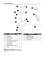
Страница 5: ...py Mounting Screw 4 preassembled H Motor Screw 6 preassembled I Lock Washer preassembled 6 J Blade 3 DESCRIPTION PART QUANTITY IMPORTANT REMINDER You must use the parts provided with this fan for prop...

Страница 6: ...ls Required for Assembly not included Electrical Tape Phillips Screwdriver Pliers Safety Glasses Stepladder and Wire Strippers Helpful Tools not included AC Tester Light Tape Measure Do It Yourself Wi...

Страница 7: ...luded Angle style mounting is best suited for angled or vaulted ceilings A longer downrod is sometimes necessary to ensure proper blade clearance Closemount mounting is more suitable for ceilings lowe...

Страница 8: ...holes in blade arm located inside of motor Attach blade J with 3 blade screws AA and fiber washers BB Repeat for remaining blades J Note Make sure to completely secure each blade J before proceeding...

Страница 9: ...ANT If using the angle mount make sure open end of mounting bracket C is installed facing the higher point of the ceiling and ensure the ceiling angle is not steeper than 19 8 For DOWNROD STYLE FAN MO...

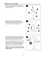
Страница 10: ...manner Take the lead wires and make sure you have pulled them all the way through the top of the downrod Start at the TOP of the hanging ball on the downrod and measure 8 in of lead wire and then cut...

Страница 11: ...in Step 4 strip 1 2 in of insulation from end of each wire WHITE BLACK GREEN and BLUE Twist stripped ends of each strand of wire within the insulation with pliers not included Install hanging ball of...

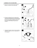
Страница 12: ...D Remove every other motor screw H and lock washer I from top of motor housing D 2 Pull wires up through hole in the middle of the canopy B Align larger holes in canopy B with 3 screws in top of moto...

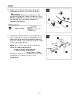
Страница 13: ...ections for remote control operation as detailed below and in the figure For each wire connection use one of the wire connectors CC making sure to screw wire connector CC on in a clockwise direction C...

Страница 14: ...r x 4 CC 3 Gently slide remote control receiver N flat side up into mounting bracket C Turn spliced taped wires upward and gently push wires and wire connectors CC into outlet box Let antenna from rem...

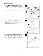
Страница 15: ...on Closemount Option 2 Align slots on glass shade K with protrusions on underside of motor housing D Turn glass shade K clockwise until it no longer turns NOTE Pull down gently on the glass shade K to...

Страница 16: ...r is encouraged to try to correct the interference by one or more of the following measures Reorient or relocate the receiving antenna Increase the separation between the equipment and receiver Connec...

Страница 17: ...fan MEDIUM speed 1 button for fan LOW speed 0 button to turn fan OFF button to turn light ON or OFF Tap button quickly to turn lights off or on Hold button down to increase or decrease lights If you...

Страница 18: ...g the reverse switch in the RIGHT position will result in upward airflow that can help move stagnant hot air off the ceiling area At least twice each year lower canopy B to check downrod A assembly an...

Страница 19: ...an approved speed control device 4 Allow fan a break in period of a few days especially when running the fan at Medium and High speeds Excessive wobbling 1 Blades are loose 2 Unbalanced blades 3 Fan n...

Страница 20: ...arranty does not cover changes in brass finish rusting pitting tarnishing corroding or peeling Brass finish fans maintain their beauty when protected from varying weather conditions Any glass provided...

Страница 21: ...TE SU RECIBO AQU Fecha de compra Preguntas problemas piezas faltantes Antes de volver a la tienda llame a nuestro Departamento de Servicio al Cliente al 1 800 527 1292 de lunes a viernes de 8 30 a m a...

Страница 22: ...eparaci n 26 Instalaci n inicial 26 Montaje del ventilador en estilo de varilla 29 Montaje del ventilador en estilo cerrado 31 Cableado 33 Instalaci n final 35 Instrucciones de funcionamiento 36 Cuida...

Страница 23: ...ilador incluidas las aspas Las modificaciones que no est n aprobadas por la parte responsable del cumplimiento podr an anular la autorizaci n del usuario para utilizar el equipo NOTA este equipo ha si...

Страница 24: ...cu l es el tama o adecuado de los conectores de cables que debe utilizar Para reducir el riesgo de incendios o descargas el ctricas no use el ventilador con dispositivos de control de velocidad para v...

Страница 25: ...1 E Cubierta de la horquilla 1 F Kit de iluminaci n LED 1 preensamblado G Tornillo de montaje de la base 4 preensamblado H Tornillo del motor 6 preensamblado I Arandela de seguridad 6 preensamblada J...

Страница 26: ...o se incluyen Cinta aislante destornillador Phillips pinzas gafas de seguridad escalera de tijera y pinzas pelacables Herramientas tiles no se incluyen Luz de prueba CA cinta m trica manual de cablead...

Страница 27: ...ntaje en ngulo es el mejor para los techos en ngulo o de b veda En ocasiones es necesaria una varilla m s larga para asegurar una adecuada separaci n de las aspas El estilo de montaje cerrado es m s a...

Страница 28: ...as aspas J con los 3 tornillos para aspa AA y arandelas para aspa BB Repita para el resto de las aspas J Nota Aseg rese de fijar completamente cada aspa J antes de proceder con la siguiente 6 7 Vuelva...

Страница 29: ...el soporte de montaje C est instalado en direcci n hacia el punto m s alto del techo y aseg rese de que el ngulo del techo no sea superior a 19 8 Para realizar el MONTAJE DEL VENTILADOR EN ESTILO DE V...

Страница 30: ...etamente a trav s de la parte superior de la varilla Comience en la parte SUPERIOR de la bola para colgar en la varilla y mida 20 32 cm de cable conductor y corte el exceso de cable con las pinzas cor...

Страница 31: ...ento del extremo de cada cable BLANCO NEGRO VERDE Y AZUL Tuerza los extremos pelados de cada filamento de cable dentro del aislamiento con pinzas no se incluyen Instale la bola para colgar en la varil...

Страница 32: ...la carcasa del motor D 2 Pase los cables hacia arriba a trav s del orificio en el centro de la base B Alinee los orificios grandes de la base B con los 3 tornillos en la parte superior de la carcasa...

Страница 33: ...namiento del control remoto de acuerdo con el dibujo que se detalla a continuaci n Para cada conexi n de cables utilice uno de los conectores de cables CC y aseg rese de atornillar el conector de cabl...

Страница 34: ...te el receptor del control remoto N con el lado plano hacia arriba en el soporte de montaje C Gire los cables empalmados o cubiertos con cinta hacia arriba y empuje suavemente los cables y los conecto...

Страница 35: ...antalla de vidrio K con protuberancias en la parte inferior de la carcasa del motor D Gire la pantalla de vidrio K en direcci n de las manecillas del reloj hasta que ya no gire NOTA Jale suavemente de...

Страница 36: ...uario que intente corregir la interferencia con una o m s de las siguientes medidas Reoriente o reubique la antena de recepci n Aumente la separaci n entre el equipo y el receptor Conecte el equipo a...

Страница 37: ...t n 2 para la velocidad MEDIA del ventilador bot n 1 para la velocidad BAJA del ventilador bot n 0 para APAGAR el ventilador bot n para ENCENDER o APAGAR la luz Toque r pidamente el bot n para encende...

Страница 38: ...de reversa en la posici n a la DERECHA crear un flujo de aire ascendente que puede ayudar a mover el aire caliente estancado fuera del rea del techo Al menos dos veces al a o baje la base B para revi...

Страница 39: ...1 Apriete todos los tornillos de las aspas 2 Reemplace el aspa 3 Reemplace por un dispositivo de control de velocidad autorizado 4 Permita que el ventilador tenga un per odo de asentamiento de un par...

Страница 40: ...bios en el acabado de lat n el xido las picaduras el deslustre la corrosi n o el descascarado Los ventiladores con acabado de lat n mantienen su belleza cuando se los protege de las condiciones clim t...

Отзывы: