background image

19

Lowes.com/harborbreeze

CARE AND MAINTENANCE

At least twice each year, lower the canopy to check the downrod assembly, and then tighten all 

screws on the fan. Clean the motor housing with only a soft brush or lint-free cloth to avoid scratching 

the finish. Clean the blades with a lint-free cloth. You may occasionally apply a light coat of furniture 

polish to wood blades for added protection. 

Important:

 Shut off the main power supply before you begin any maintenance task. Do not use water 

or a damp cloth to clean the fan.


TROUBLESHOOTING

PROBLEM

POSSIBLE CAUSE

CORRECTIVE ACTION

The fan does not 

move.

1.  The reverse switch is not 

engaged.

2.  The wall switch is turned off. 

3.  The power is off or the fuse 

(breaker) is blown.

4.  There is a faulty wire 

connection.

1.  Firmly push the reverse switch to 

either the left or right.

2.  Make sure the wall switch is turned 

on.

3.  Turn the power on or check the fuse 

(breaker).

4.  Turn the power off and check all 

connections at the ceiling outlet box.

The fan is noisy.

1.  The blades are loose. 


2.  There is a cracked blade.
3.  The wall control is not 

compatible with the fan.

4.  The break-in period has not 

surpassed. 

5.  The outlet box is not secure. 

6.  The mounting bracket is not 

secure.

1.  Check and tighten all screws that 

hold the fan blades to the blade 

arms and the motor.

2.  Replace the cracked blade.
3.  Do not use a full range dimmer 

switch to control the fan speed.

4.  Run the fan continuously for 24 - 48 

hours on medium or high speed for 

a “break in” period.

5.  Ensure the outlet box is secured to 

the building structure.

6.  Ensure the mounting bracket is 

secured to the outlet box and that 

the screws are tight.

Содержание PACIFIC GROVE 40101

Страница 1: ...ST Monday Thursday 8 a m 5 p m EST Friday 1 ATTACH YOUR RECEIPT HERE Serial Number _________________________ Purchase Date _________________________ Lowes com harborbreeze Harbor Breeze is a registered trademark of LF LLC All Rights Reserved EB13354 ITEM 0451809 PACIFIC GROVE CEILING FAN MODEL 40101 Español p 23 LISTED FOR WET LOCATION ...

Страница 2: ...nts 4 Safety Information 5 Preparation 6 Initial Installation 7 Standard or Angle Mounting Instructions 9 Closemount Instructions 12 Final Installation 15 Operating Instructions 18 Care and Maintenance 19 Troubleshooting 19 Limited Lifetime Warranty 21 Replacement Parts List 22 ...

Страница 3: ...Canopy preassembled to Mounting Bracket C 1 C Mounting Bracket 1 D Yoke Cover 1 E Motor Assembly 1 F Blade 5 G Switch Housing 1 H Blade Arm 5 I Fitter Plate 1 J Canopy Cover preassembled to Canopy B 1 K Switch Housing Plate preassembled to the Motor Assembly E 1 A I K E F G H B J C D ...

Страница 4: ...sembled to Motor Assembly E Closemount Screw Qty 3 preassembled to Motor Assembly E Mounting Bracket Screw Qty 4 preassembled to Mounting Bracket C Blade Screw Qty 15 1 extra Blade Washer Qty 15 1 extra Spring Washer Qty 10 preassembled to Motor Screw AA 1 extra Rubber Washer Qty 15 1 extra Switch Housing Plate Screw Qty 3 preassembled to Switch Housing Plate K Switch Housing Screw Qty 3 preassemb...

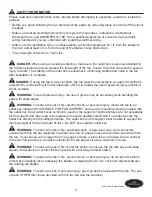
Страница 5: ... necessary while handling fan parts with sharp edges WARNING To reduce the risk of fire electric shock or personal injury mount the fan to an outlet box marked ACCEPTABLE FOR FAN SUPPORT and use the mounting screws provided with the outlet box Most outlet boxes commonly used for the support of lighting fixtures are not acceptable for fan support and may need to be replaced Consult a qualified elec...

Страница 6: ...e all parts are present Compare all parts with the package contents list and hardware contents list If any part is missing or damaged do not attempt to assemble the product After opening the top of the carton remove the mounting hardware package from the foam inserts then remove the motor from the packaging and place it on a soft surface such as a carpet to avoid damage to the finish Estimated Ass...

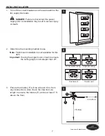
Страница 7: ... 1 2 Determine the mounting method to use Note Flushmount installation is not available for this item Important If using the angle mount check to ensure the ceiling angle is not steeper than 23 2 Downrod Mounting Flushmount Closemount Angle Mounting 3 Ensure the blades F will be at least 30 in from any obstructions Also check the downrod A length to ensure the blades F will be at least 7 ft above ...

Страница 8: ...ounting Bracket Screw x 2 4 B HH C 5 Feed black blue and white wires from the plug on the mounting bracket C up through the hole in the top 6 Remove and discard the three rubber stoppers and the five plastic spacers from the underside of the motor assembly E For Standard or Angle Mounting Instructions continue to page 9 For Closemount Instructions proceed to page 12 6 Plastic Spacer Rubber Stopper...

Страница 9: ...gether with wire connectors BB Note The Black wire is hot power for the fan The White wire is common The Blue wire is hot power for light sold separately wiring instructions will differ if optional light kit is purchased Refer to light kit manufacturer s instructions Wiring instructions will differ if optional light kit is purchased Refer to light kit manufacturer s instructions The Green wire is ...

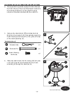
Страница 10: ...rovided with the outlet box 5 Remove the downrod pin EE and downrod clip DD from the downrod A Then partially loosen the motor housing set screws FF in the yoke at the top of the motor assembly E Hardware Used DD Downrod Clip x 1 EE Downrod Pin x 1 FF Motor Housing Set Screw x 2 6 Place the downrod A into the canopy B and yoke cover D Feed the wire harness from the motor assembly E through the dow...

Страница 11: ...ing bracket C Rotate the downrod A until the slot on the downrod A engages the tab on the mounting bracket C DANGER Be careful when aligning the tab to the slot If not fully engaged the fan may fall which may result in serious injury or death 9 Connect the green wires from the downrod A and the mounting bracket C to the bare green ground supply wire using a wire connector BB Then wrap electrical t...

Страница 12: ...he Black wire is hot power for the fan The White wire is common The Blue wire is hot power for light sold separately wiring instructions will differ if optional light kit is purchased Refer to light kit manufacturer s instructions Wiring instructions will differ if optional light kit is purchased Refer to light kit manufacturer s instructions The Green wires are the ground wires If house wires are...

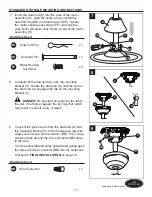
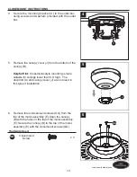
Страница 13: ...nt Closemount style mounting is more suitable for ceilings lower than 8 ft high The downrod A and canopy cover J are not used in this type of installation 6 Remove three closemount screws GG from the top of the motor assembly E Align the canopy B with the holes in the top of the motor assembly E Secure the canopy B to the top of the motor assembly E with the closemount screws GG Hardware Used GG C...

Страница 14: ...14 Lowes com harborbreeze CLOSEMOUNT INSTRUCTIONS 7 Raise the fan and place the canopy B on the hook on the mounting bracket C B C 7 ...

Страница 15: ...m the mounting bracket C to the pin connector at the end of the wire harness 3 Align the key slots on the canopy B with the heads of the mounting bracket screws HH preassembled on mounting bracket C Lift the canopy B up and rotate it clockwise until the mounting bracket screws HH engage the key slots Hardware Used HH Mounting Bracket Screw x 2 2 Note Downrod A is shown referenced but instructions ...

Страница 16: ...nd three rubber washers LL to attach one blade arm H to a blade F Tighten each blade screw II starting with the one in the middle Repeat for remaining blades F Hardware Used II Blade Screw x 15 Blade Washer x 15 Rubber Washer x 15 6 Slide the two holes of a blade arm H over the two motor screws AA preassembled on motor housing E Tighten motor screws AA to secure blade arm H Repeat for remaining bl...

Страница 17: ...Attach the fitter plate I to the switch housing plate K by twisting the fitter plate I until the loosened switch housing plate screws MM engage the key slots on the fitter plate I Re install the third switch housing plate screw MM into the closed hole in the fitter plate I and securely tighten all three switch housing plate screws MM Hardware Used MM Switch Housing Plate Screw x 3 9 Cconnect the p...

Страница 18: ...hich will result in downward airflow creating a wind chill effect 2B In cooler weather push the reverse switch right to display a Snowflake icon which will result in upward airflow that can help move stagnant hot air off the ceiling area Important The reverse switch must be set either completely left or right in order for the fan to function correctly If the reverse switch is set in the middle pos...

Страница 19: ...s blown 4 There is a faulty wire connection 1 Firmly push the reverse switch to either the left or right 2 Make sure the wall switch is turned on 3 Turn the power on or check the fuse breaker 4 Turn the power off and check all connections at the ceiling outlet box The fan is noisy 1 The blades are loose 2 There is a cracked blade 3 The wall control is not compatible with the fan 4 The break in per...

Страница 20: ...tighten all screws that hold the fan blades to the blade arms and the blade arms to the motor 2 Switch one blade with a blade from the opposite side Or balance the fan using a balancing kit not supplied 3 Turn off the power Loosen the canopy and verify that the mounting bracket is secure to the electrical outlet box The bracket must be flush without movement against the outlet box 4 Use a longer d...

Страница 21: ...alid Due to varying climate conditions this warranty does not cover any changes in brass finish including rusting pitting corroding tarnishing or peeling Brass finishes of this type give their longest useful life when protected from varying weather conditions Any glass provided with this fan is not covered by the warranty Any replacement of defective parts from the ceiling fan must be reported wit...

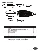
Страница 22: ...CEMENT PARTS LIST For replacement parts call the customer service department at 1 800 643 0067 8 a m 6 p m EST Monday Thursday 8 a m 5 p m EST Friday PART DESCRIPTION PART A Downrod 0451809 A B Canopy 0451809 B C Mounting Bracket 0451809 C H Blade Arm 0451809 H F Blade 0451809 F HW Hardware Bag 0451809 HW A B C H F HW ...

Страница 23: ...F LLC Todos los derechos reservados ADJUNTE SU RECIBO AQUÍ Número de serie _________________________ Fecha de compra _________________________ Preguntas problemas piezas faltantes Antes de volver a la tienda llame a nuestro Departamento de Servicio al Cliente al 1 800 643 0067 de lunes a jueves de 8 a m a 6 p m y los viernes de 8 a m a 5 p m hora estándar del Este ...

Страница 24: ...27 Preparación 28 Instalación inicial 29 Instrucciones de montaje en ángulo y estándar 31 Instrucciones para montaje cerrado 34 Instalación final 37 Instrucciones de funcionamiento 40 Cuidado y mantenimiento 41 Solución de problemas 41 Garantía limitada de por vida 43 Lista de piezas de repuesto 44 ...

Страница 25: ... de montaje C 1 C Abrazadera de montaje 1 D Cubierta de la horquilla 1 E Ensamble del motor 1 F Aspa 5 G Carcasa del interruptor 1 H Brazo del aspa 5 I Placa de soporte 1 J Cubierta de la base preensamblada en la base B 1 K Placa de la carcasa del interruptor preensamblado en el ensamblaje del motor E 1 A I K E F G H B J C D ...

Страница 26: ...o de montaje cerrado Cant 3 preensamblado en el ensamblaje del motor E Tornillo de la abrazadera de montaje Cant 4 preensamblado en la abrazadera de montaje C Tornillo del aspa Cant 15 y 1 adicional Arandela del aspa Cant 15 y 1 adicional Arandela de resorte Cant 10 preensamblado en la tornillo del motor AA y 1 adicional Arandela de goma Cant 15 y 1 adicional Tornillo de la placa de la carcasa del...

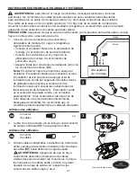
Страница 27: ...filosos ADVERTENCIA Para reducir el riesgo de incendios descargas eléctricas o lesiones personales instale el ventilador en una caja de salida marcada como APTA PARA SOSTENER UN VENTILADOR y utilice los tornillos de montaje incluidos en la caja de salida La mayoría de las cajas de salida que se usan comúnmente para sostener ensambles de iluminación no son aptas para sostener un ventilador y puede ...

Страница 28: ...de tener todas las piezas Compare todas las piezas con la lista del contenido del paquete y con la lista de aditamentos No intente ensamblar el producto si falta alguna pieza o si estas están dañadas Después de abrir la parte superior de la caja retire el paquete de aditamentos para montaje de los accesorios de espuma Luego quite el motor del ensamble y colóquelo en una superficie suave como una a...

Страница 29: ...a varilla más larga no incluida El montaje en ángulo es mejor para los techos en ángulo o de bóveda En ocasiones es necesaria una varilla más larga para asegurar una adecuada separación de las aspas Nota La instalación de montaje al ras no está disponible para este artículo Importante Si realiza el montaje en ángulo verifique que el ángulo del techo no tenga una inclinación superior a los 23 2 Mon...

Страница 30: ...ra de montaje x 2 5 Pase el conductor negro el conductor azul y el conductor blanco del enchufe en la abrazadera de montaje C hacia el orificio en la parte superior 6 Retire y deseche los tres topes de goma y los cinco separadores de plástico del lado inferior del ensamble del motor E Si desea las Instrucciones de montaje estándar o en ángulo continúe a la página 31 Si desea las instrucciones para...

Страница 31: ...a El conductor negro le proporciona energía al ventilador El conductor blanco es el conductor común El conductor azul le proporciona energía al kit de iluminación se vende por separado las instrucciones de cableado serán distintas si compra el kit de iluminación opcional Consulte las instrucciones del fabricante del kit de iluminación El conductor verde es el conductor de puesta a tierra y se cone...

Страница 32: ...ador de la varilla EE y el sujetador de la varilla DD de la varilla A Luego afloje parcialmente los tornillos de ajuste de la carcasa del motor FF que se encuentran en la horquilla de la parte superior de la carcasa del motor E Aditamentos utilizados DD Sujetador de la varilla x 1 EE Pasador de la varilla x 1 FF Tornillo de ajuste de la carcasa del motor x 2 6 Inserte la varilla A a través de la b...

Страница 33: ... de la bola con la lengüeta de la abrazadera de montaje C La varilla no debe girar si esto se hace correctamente PELIGRO Si no alinea la ranura de la bola con la lengüeta pueden producirse lesiones graves o la muerte 9 Conecte los conductores verdes de la varilla A y de la abrazadera de montaje C al conductor de suministro desnudo verde de puesta a tierra con un conector para cables BB Luego Cubra...

Страница 34: ...abrazadera de montaje C al conductor de suministro negro Asegure todas las conexiones del cableado junto con los conectores de cables BB Nota El conductor negro le proporciona energía al ventilador El conductor blanco es el conductor común El conductor azul le proporciona energía al kit de iluminación se vende por separado las instrucciones de cableado serán distintas si compra el kit de iluminaci...

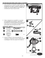
Страница 35: ...rior de la base B Consejo útil El estilo de montaje cerrado es más adecuado para los techos de menos de 2 44 m 8 pies de alto La varilla la bola para colgar y la cubierta de la base no se utilizan en este tipo de instalación 6 Retire los tornillos de montaje cerrado GG de la parte superior del ensamble del motor E Alinee la base B con los orificios de la parte superior del ensamblaje del motor E F...

Страница 36: ...36 Lowes com harborbreeze INSTRUCCIONES PARA MONTAJE CERRADO 7 Levante el ventilador y coloque la base B en el gancho de la abrazadera de montaje C B C 7 ...

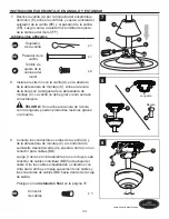
Страница 37: ...l pasador al extremo del arnés de cableado 3 Alinee los orificios de la base B con la cabeza de los tornillos de la abrazadera de montaje HH preinstalados en la abrazadera de montaje C Levante la base B y gírela en dirección de las manecillas del reloj hasta que los tornillos de la abrazadera de montaje HH calcen por completo en los chaveteros Aditamentos utilizados HH Tornillo de la abrazadera de...

Страница 38: ...razo del aspa H a un aspa F Luego apriete cada uno de los tornillos para aspas II comience por el que está en el centro Repita el procedimiento con el resto de las aspas F Aditamentos utilizados II Tornillo del aspa x 15 Arandela del aspa x 15 Arandela de goma x 15 6 Deslice los dos orificios en el brazo del aspa H sobre los tornillos del motor AA preensambladas en la carcasa del motor E Apriete l...

Страница 39: ...bicando los orificios del chavetero de la placa de soporte I en los dos tornillos sueltos de la placa de la carcasa del interruptor MM Gire la place de soporte I hasta que las cabezas de los tornillos calcen con los chaveteros Vuelva a instalar el tercer tornillo de la placa de la carcasa del interruptor MM en el orificio cerrado de la place de soporte I y apriete firmemente los tres tornillos de ...

Страница 40: ... el interruptor de reversa hacia la izquierda y verá un icono de un sol lo que creará un flujo de aire descendente que generará un efecto de viento refrescante 2B En climas más fríos deslice el interruptor de reversa hacia la derecha y verá un icono de copo de nieve que creará un flujo de aire ascendente que puede ayudar a mover el aire caliente estancado fuera del área del techo Importante El int...

Страница 41: ...eva firmemente el interruptor de reversa hacia la izquierda o hacia la derecha 2 Asegúrese de que el interruptor de pared esté encendido 3 Encienda el suministro eléctrico o verifique el fusible interruptor 4 Desactive la alimentación eléctrica y revise todas las conexiones de la caja de salida del techo El ventilador hace ruido 1 Las aspas están sueltas 2 Hay una aspa partida 3 El control de pare...

Страница 42: ...ornillos que sostienen las aspas del ventilador en los brazos de las aspas y en el motor 2 Intercambie un aspa con otra del lado opuesto O equilibre el ventilador mediante el kit de equilibrio no se incluye 3 Desconecte el suministro de electricidad Afloje la base y verifique que la abrazadera de montaje esté asegurada en la caja de salida eléctrica La abrazadera debe estar al ras de la caja de sa...

Страница 43: ...la garantía Debido a las cambiantes condiciones climáticas esta garantía no cubre cambios en el acabado de latón incluidos la oxidación las picaduras la corrosión el deslustre o el descascarado Los acabados de latón de este tipo proporcionan una vida útil más prolongada si se los protege de las cambiantes condiciones climáticas La garantía no cubre los elementos de vidrio incluidos con este ventil...

Страница 44: ...es a viernes de 8 a m a 6 p m y los viernes de 8 a m a 5 p m hora estándar del Este PIEZA DESCRIPCIÓN PIEZA A Varilla 0451809 A B Base 0451809 B C Abrazadera de montaje 0451809 C H Brazo del aspa 0451809 H F Aspa 0451809 F HW Kit de aditamentos 0451809 HW A B C H F HW Impreso en China Harbor Breeze es una marca registrada de LF LLC Todos los derechos reservados ...

Отзывы: