background image

4

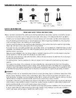
HARDWARE CONTENTS 

SAFETY INFORMATION

(not shown actual size)

Lowes.com/harborbreeze

AA

BB

CC

DD

READ AND SAVE THESE INSTRUCTIONS

Please read and understand this entire manual before attempting to assemble, operate or install the product. 
.   All electrical connections must comply with local codes, ordinances or the National Electric Code (NEC). 

    Contact your municipal building department to inquire about your local codes, permits and/or inspections.  
.   Turn off electricity at main fuse box (or circuit breaker box) before beginning installation by removing fuse 

    or by removing th fuse or by switching off circuit breaker.
.   Do not connect this fixture to an electrical system that does not provide a means for equipment grounding. 

    Never use a fixture in a two-wire system that is not grounded.  
.   If you are not sure your lighting system has a grounding means, do not attempt to install this fixture. Contact 

    a qualified, licensed electrician for information regarding proper grounding methods as required by the local 

    electrical code in your area.   
.   Make sure the installation site you choose allows a minimum clearance of 7 ft. from the blades to the floor 

    and at least 30 in. from the ends of the blades to any obstruction. 
.   If a dimmer control switch is used with this fixture, obtain professional advice to determine the correct type 

    and electrical rating required.  
.   The lighting fixture must be positioned so there is at least 1.64 ft. between the bulb and any illuminated 

    surface.    
.   For supply connections, if the conductor of a fan is identified as a grounded conductor, then it should be 

    connected to a grounded conductor power supply. If the conductor of a fan is identified as an ungrounded 

    conductor, then it should be connected to an ungrounded conductor power supply. If the conductor of a fan 

    is identified for equipment grounding, then it should be connected to an equipment-grounding conductor.    

.   Installing a fixture into an electrical system without a proper grounding means could allow metal parts of the 

    fixture to carry electrical currents. If any of the fixture wires, wire connections or splices are broken, cut or 

    loose during the mounting or normal operation of the fixture, under such conditon, anyone coming in contact 

    with the fixture is subject to electrical shock, which could cause serious injury or death.     
.   Connection of the bare or green fixture ground wire to the black or white house wires may allow metal parts 

    of the fixture to carry electrical currents. Under this condition anyone coming in contact with the fixture will 

    receive electrical shock, which could cause serious injury or death.       
.   Be careful not to damage or cut the wire insulation (covering) during fixture installation. Do not permit wires 

    to have contact with any surface having a sharp edge. Doing so may damage or cut the wire insulation, 

    which could cause serious injury or death from electric shock.       

 DANGER

Fob

Qty. 2

Wire Connector

Qty. 4

Blade Screw

Qty. 15 + 1 extra

Motor Screw

Qty. 10 + 1 extra

Содержание LAKE PLACIDO CPK1261

Страница 1: ...tions problems missing parts Before returning to your retailer call our customer service department at 1 800 643 0067 8 a m 6 p m EST Monday Thursday 8 a m 5 p m EST Friday EB14429 ATTACH YOUR RECEIPT...

Страница 2: ...nitial Instructions Standard Angle Mounting Instructions Flushmount Instructions Wiring Instructions Final Instructions Operating Instructions Care and Maintenance Troubleshooting Limited Lifetime War...

Страница 3: ...embled on Mounting Bracket A 4 E Coupling Cover 1 R Clevin Pin preassembled on Coupling P 1 F Motor Housing 1 S Hairpin Clip preassembled on Coupling P 1 G Blade Iron 5 T Coupling Screw preassembled o...

Страница 4: ...positioned so there is at least 1 64 ft between the bulb and any illuminated surface For supply connections if the conductor of a fan is identified as a grounded conductor then it should be connected...

Страница 5: ...SURPLQHQW ZDUQLQJ GHYLFH VXFK DV D WDJ WR WKH VHUYLFH SDQHO R QRW XVH EXOEV KDYLQJ D ZDWWDJH JUHDWHU WKDQ WKH PD LPXP YDOXH VWDWHG RQ WKH IL WXUH DQG LQ WKLV PDQXDO 8VLQJ D KLJKHU ZDWWDJH EXOE WKDQ V...

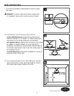
Страница 6: ...may want to use a longer downrod not included B Angle Mounting Angle style mounting is best suited for angled or vaulted ceilings A longer downrod is sometimes necessary to ensure proper blade clearan...

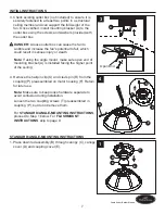
Страница 7: ...p loose hardware separate to avoid confusion during installation Loosen the two coupling screws T preassembled in coupling P but do not remove them Note If using the angle mount make sure open end of...

Страница 8: ...p with the tab on the mounting bracket A This will allow for hands free wiring Proceed to WIRING on page 10 DANGER Be careful when aligning the tab to the slot If not fully engaged there is a possibil...

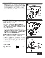
Страница 9: ...F Guide motor wires through the base of the canopy C then attach canopy C to motor housing F with previously removed screws Tighten securely 3 Raise assembly and temporarily place one side of canopy C...

Страница 10: ...e electricity is turned off at the main fuse box before hanging WARNING If you are not sure if the outlet box is grounded contact a licensed electrician for advice as it must be grounded for safe oper...

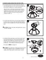
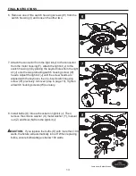
Страница 11: ...tall previously removed mounting screws then tighten all screws securely 2 Position one blade iron G under blade H Insert three blade screws BB through blade H and into blade iron G Tighten each blade...

Страница 12: ...d with the keyholes then re insert mounting screw V previously removed step 4 page 12 Tighten all mounting screws V securely Lowes com harborbreeze 3 Secure one blade blade iron assembly to the flywhe...

Страница 13: ...until the screw heads are aligned with the keyholes then re insert switch housing screw W previously removed step 6 page 13 Tighten all switch housing screws W securely 8 Install bulbs O into each so...

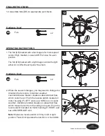
Страница 14: ...L INSTRUCTIONS 9 Install the glass bowl K into light case L aligning the holes in glass bowl K and light case L Note You must align the rim of motor housing F with the rim of light case L to ensure pr...

Страница 15: ...e when switch is in the middle FINAL INSTRUCTIONS Hardware Used DD Fob x 2 Hardware Used DD Fob x 2 12 DD OPERATING INSTRUCTIONS DD 1 2 When the season changes you may want to change the direction the...

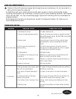
Страница 16: ...ws to the outlet box and or secure outlet box 2 Set screw in downrod assembly is loose 2 Tighten the set screw in the downrod assembly seated in canopy tabs 3 Fan hanger ball is not properly 3 Turn po...

Страница 17: ...w speed wobble should disappear 10 Fan not securely mounted 10 Make sure canopy and mounting bracket are tightened securely to ceiling joist 1 Power turned off fuse blown or circuit breaker tripped 1...

Страница 18: ...Due to varying climatic conditions this warranty does not cover changes in brass finish rusting pitting tarnishing corroding or peeling Brass finish fans maintain their beauty when protected from var...

Страница 19: ...A B C E J I N M AA BB CC DD L K G H D A Mounting Bracket A102 0132070 B Downrod Assembly A103 0156348 C Canopy A101 0348348 D Canopy Cover A108 0260348 E Coupling Cover A106 1262348 G Blade Iron A143...

Отзывы: