background image

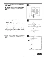
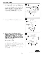
Locate motor screws (Q) and lock washers (R) 
removed in Step 5, page 7.

Insert two motor screws (Q) along with lock washers 
(R) through one blade arm (I) to attach blade arm (I) 
to motor. Tighten motor screws (Q) securely. 
Repeat with remaining blade arms (I), making sure 
to completely secure each blade arm (I) before 
proceeding with the next.

 3. 

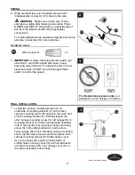
 4.  Remove three screws from outer edge of switch 

housing plate (F).

Partially loosen two screws in fitter plate on 
underside of motor housing (E) and remove the 
other screw. Align slotted holes in switch housing 
plate (F) with loosened screws, allowing male plug 
from motor housing (E) to come through hole in 
switch housing plate (F). Twist switch housing plate 
(F) to lock. Re-insert the screw that was removed 
and securely tighten all three screws. 

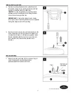
Partially insert three blade screws (AA) along with 
three fiber blade washers (BB) to attach one blade 
arm (I) to a blade (J). Then, tighten each blade 
screw (AA) starting with the one in the middle. 
Repeat with remaining blades (J).

 2. 

Blade Screw                                         x 15

Fiber Blade Washer                              x 15  

2

AA

BB

I

J

FINAL INSTALLATION

Hardware Used

AA

BB

3

J

II

R

Q

12

Lowes.com/harborbreeze

Fitter 
Plate

Male 

Plug

IU

IF

IV

IE

4

Содержание E-TM52BNK5LED

Страница 1: ... MODEL E TM52BNK5LED Questions problems missing parts Before returning to your retailer call our customer service department at 1 800 643 0067 8 a m 6 p m EST Monday Thursday 8 a m 5 p m EST Friday ATTACH YOUR RECEIPT HERE Serial Number Purchase Date EB14593 1 Lowes com harborbreeze Español p 19 ITEM 0062325 ...

Страница 2: ...d to the factory for repairs it must be shipped in its original packaging to ensure proper protection against damage that might exceed the initial cause for return Make sure all electrical connections comply with local codes ordinances the National Electrical Code and ANSI NFPA 70 1999 Hire a qualified electrician or consult a do it yourself wiring handbook if you are unfamiliar with installing el...

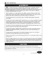
Страница 3: ...rresponding fan lead wires consult an electrician for the proper size wire connectors to use To reduce the risk of fire or electrical shock do not use the fan with any solid state speed control device or control fan speed with a full range dimmer switch To reduce the risk of fire electrical shock or personal injury do not bend the blade arms when installing them balancing the blades or cleaning th...

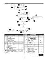
Страница 4: ...ade Arm 5 J Blade 5 K Pull Chain Extension 2 L Light Kit Fitter 1 DESCRIPTION PART QUANTITY M Finial Plate preassembled 1 N Finial preassembled 1 O Pin preassembled 1 P Clip preassembled 1 Q Motor Screw 10 preassembled R Lock Washer 10 preassembled S Canopy Mounting Screw 2 preassembled T Threaded Washer 1 preassembled U Switch Housing Screw 3 preassembled V Fitter Plate Screw 3 preassembled DESCR...

Страница 5: ...ched to the building structure and can support the full weight of the fan Failure to do this can result in serious injury or death The stability of the outlet box is essential in minimizing wobble and noise in the fan after installation is complete CAUTION Be sure outlet box is properly grounded and a ground wire green or bare is present After opening top of carton remove mounting hardware package...

Страница 6: ...rbreeze J ON OFF ON OFF 3 2 1 A B 7 ft min 30 in min INITIAL INSTALLATION Determine mounting method to use A Standard mount B Angle mount IMPORTANT If using the angle mount ensure the ceiling angle is not steeper than 19 Helpful Hint Standard mounting is best suited for ceilings 8 ft high or higher For taller ceilings you may want to use a longer downrod not included Angle mounting is best suited ...

Страница 7: ...discard the plastic motor blocks INITIAL INSTALLATION Secure mounting bracket C to outlet box not included using screws spring washers and flat washers provided with the outlet box NOTE It is very important you use the proper hardware when installing the mounting bracket C as this will support the fan IMPORTANT If using the angle mount make sure open end of mounting bracket C is installed facing t...

Страница 8: ...e the lead wires and make sure you have pulled them all the way through the top of the downrod Start at the TOP of the ball on the downrod and measure 8 in of lead wire and then cut the excess wire off with wire cutters not included NOTE If you do not cut back the lead wires Steps 4 and 5 are not necessary and you may proceed to Step 6 instead 4 3 Slip downrod A into yoke align holes and re instal...

Страница 9: ...fan are designed to accept only one 12 gauge house wire and two lead wires from the fan If your house wire is larger than 12 gauge or there is more than one house wire to connect to the two fan lead wires consult an electrician for the proper size wire connectors to use CAUTION Be sure outlet box is properly grounded and a ground green or bare wire is present WARNING If house wires are different c...

Страница 10: ...he other independent wall switch for the light Connect WHITE wire from fan to WHITE wire from ceiling Connect all GROUND GREEN wires together from fan on downrod A and mounting bracket C to BARE GREEN wire from ceiling NOTE BLACK wire is hot power for fan BLUE wire is hot power for light kit WHITE wire is common for fan and light kit BARE GREEN wire is ground 1B FAN CONTROLLED BY PULL CHAIN LIGHT ...

Страница 11: ...clockwise until it stops Wrap electrical tape not included around each individual wire connector CC down to the wire WARNING Make sure no bare wire or wire strands are visible after making connections Place GREEN and WHITE connections on opposite side of box from the BLACK and BLUE if applicable connections Turn spliced taped wires upward and gently push wires and wire connectors CC into outlet bo...

Страница 12: ...ve the other screw Align slotted holes in switch housing plate F with loosened screws allowing male plug from motor housing E to come through hole in switch housing plate F Twist switch housing plate F to lock Re insert the screw that was removed and securely tighten all three screws Partially insert three blade screws AA along with three fiber blade washers BB to attach one blade arm I to a blade...

Страница 13: ...h threaded rod allowing pull chains to come through corresponding holes in glass shade H Push up gently on glass shade H until threaded rod comes through hole Secure glass shade H with threaded washer previously removed NOTE Do NOT overtighten threaded washer T as glass may crack or break Thread pull chains through appropriate holes in finial plate M and push up on finial plate M allowing threaded...

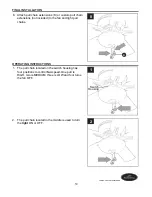
Страница 14: ...three is LOW and four turns the fan OFF 1 8 Attach pull chain extensions K or custom pull chain extensions not included to the fan and light pull chains Switch Housing FINAL INSTALLATION 8 K OPERATING INSTRUCTIONS 1 2 The pull chain located in the middle is used to turn the light ON or OFF 2 14 Lowes com harborbreeze ...

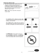
Страница 15: ...STRUCTIONS Switch Housing 3 3A In warmer weather setting the reverse switch in the LEFT position will result in downward airflow creating a wind chill effect 3B In cooler weather setting the reverse switch in the RIGHT position will result in upward airflow that can help move stagnant hot air off the ceiling area 3C IMPORTANT Reverse switch must be set either completely to the RIGHT or completely ...

Страница 16: ...s on page 13 Noisy operation 1 Blades are loose 2 Cracked blade 3 Full range dimmer switch 4 Fan is new Warning Before beginning work shut off the power supply to avoid electrical shock TROUBLESHOOTING 1 Tighten all blade screws 2 Replace blade 3 Replace with an approved speed control device 4 Allow fan a break in period of a few days especially when running the fan at Medium and High speeds 16 Lo...

Страница 17: ...istributor assumes no responsibility whatsoever for fan installation during the limited lifetime warranty Any service performed by an unauthorized person will render the warranty invalid Due to varying climatic conditions this warranty does not cover changes in brass finish rusting pitting tarnishing corroding or peeling Brass finish fans maintain their beauty when protected from varying weather c...

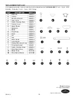
Страница 18: ... PART DESCRIPTION PARTS A Downrod B Canopy C Mounting Bracket D Yoke Cover F Switch Housing Plate G Canopy Cover H Glass Shade I Blade Arm J Blade M Finial Plate N Finial O Pin P Clip Q Motor Screw R Lock Washer S Canopy Mounting Screw T Threaded Washer U Switch Housing Screw V Fitter Plate Screw AA Blade Screw BB Fiber Blade Washer PWLI1410 62325 A 62325 B 62325 C 62325 D 62325 F 62325 G 62325 H ...

Страница 19: ...eguntas problemas piezas faltantes Antes de volver a la tienda llame a nuestro Departamento de Servicio al Cliente al 1 800 643 0067 de lunes a jueves de 8 a m a 6 p m y los viernes de 8 a m a 5 p m hora estándar del Este ADJUNTE SU RECIBO AQUÍ Número de serie Fecha de compra 19 Lowes com harborbreeze ARTÍCULO 0062325 E192641 LISTED ...

Страница 20: ...n su empaque original para asegurar una protección adecuada contra daños que puedan aumentar la causa inicial de la devolución Asegúrese de que todas las conexiones eléctricas cumplan con los códigos y ordenanzas locales el Código Eléctrico Nacional la norma ANSI NFPA 70 1999 Si no está familiarizado con la instalación del cableado eléctrico contrate a un electricista calificado o consulte un manu...

Страница 21: ...ista cuál es el tamaño adecuado de los conectores de cables que debe utilizar Para reducir el riesgo de incendios o descargas eléctricas no use el ventilador con dispositivos de control de velocidad para ventiladores de estado sólido ni controle la velocidad del ventilador con un regulador de intensidad de rango completo Para reducir el riesgo de incendio descarga eléctrica o lesiones personales n...

Страница 22: ...sión de la cadena de tiro 2 L Soporte del kit de iluminación 1 DESCRIPCIÓN PIEZA CANTIDAD M Placa del remate 1 preensamblada N Remate preensamblado 1 O Pasador preensamblado 1 P Sujetador preensamblado 1 Q Tornillo del motor 10 preensamblado R Arandela de seguridad 10 preensamblada S Tornillo de montaje de la base 2 preensamblado T Arandela roscada 1 preensamblada U Tornillo de la carcasa del 3 in...

Страница 23: ...ilador El incumplimiento de dicho paso podría provocar lesiones graves o la muerte La estabilidad de la caja de salida es fundamental para minimizar el tambaleo y el ruido en el ventilador una vez que la instalación esté completa PRECAUCIÓN Asegúrese de que la caja de salida tenga la debida puesta a tierra y de que haya un conductor verde o desnudo de puesta a tierra Después de abrir la parte supe...

Страница 24: ...taje estándar B Montaje en ángulo IMPORTANTE Si realiza el montaje en ángulo verifique que el ángulo del techo no tenga una inclinación superior a los 19 Consejo útil El montaje estándar es mejor para los techos de 2 44 m de alto o más altos Para techos más altos se recomienda utilizar una varilla más larga no incluida El montaje en ángulo es mejor para los techos en ángulo o de bóveda En ocasione...

Страница 25: ...opes plásticos del motor INSTALACIÓN INICIAL Asegure el soporte de montaje C a la caja de salida no se incluye con los tornillos las arandelas de resorte y las arandelas planas provistas con la caja de salida NOTA Es muy importante que use los aditamentos adecuados para instalar el soporte de montaje C ya que este soportará el ventilador IMPORTANTE Si realiza el montaje en ángulo asegúrese de que ...

Страница 26: ...manera Tome los cables conductores y asegúrese de jalarlos completamente a través de la parte superior de la varilla Comience en la parte SUPERIOR de la bola en la varilla y mida 20 32 cm de cable y corte el exceso con las pinzas cortacables no se incluyen NOTA Si no cortó los cables los Pasos 4 y 5 no son necesarios y puede proceder con el Paso 6 en su lugar 4 3 Deslice la varilla A en la horquil...

Страница 27: ... soportar solo un cable de la casa de calibre 12 y dos cables conductores del ventilador Si el cable de la casa es de un calibre superior a 12 o hay más de un cable de la casa para conectar a los dos cables conductores del ventilador pregúntele a un electricista cuál es el tamaño adecuado de los conectores de cables que debe utilizar PRECAUCIÓN Asegúrese de que la caja de salida tenga la debida pu...

Страница 28: ...ADOS POR DOS INTERRUPTORES DE PARED Conecte el cable NEGRO del ventilador al cable NEGRO o ROJO del interruptor de pared independiente del ventilador Conecte el conductor AZUL del ventilador al conductor NEGRO o ROJO del otro interruptor de pared independiente para la luz Conecte el cable BLANCO del ventilador al cable BLANCO del techo Conecte los cables de PUESTA A TIERRA VERDES desde la varilla ...

Страница 29: ...e se detenga 2 IMPORTANTE Si usa un regulador de intensidad de rango completo no se incluye para controlar la velocidad del ventilador provocará un zumbido intenso del ventilador Para reducir el riesgo de incendios o descargas eléctricas NO use un regulador de intensidad de rango completo para controlar la velocidad del ventilador 3 CABLEADO Conector de cables x 4 Aditamentos utilizados CC Regulad...

Страница 30: ...laca de la carcasa del interruptor F con los tornillos aflojados en la placa de soporte V permitiendo que el enchufe macho de la carcasa del motor E pase a través el orificio en la placa de la carcasa del interruptor F Gire la placa de la carcasa del interruptor F para bloquearla Vuelva a insertar el tornillo que retiró y apriete bien los tres tornillos Inserte parcialmente tres tornillos para las...

Страница 31: ...CIÓN FINAL 5 L F E I U 6 L N M I T 7 L N M I T 31 Lowes com harborbreeze H Varilla roscada Alinee el orificio central de la pantalla de vidrio H con la varilla roscada permitiendo que las cadenas de tiro pasen a través de los orificios correspondientes en la pantalla de vidrio H Empuje la pantalla de vidrio H suavemente hacia arriba hasta que la varilla roscada pase por el orificio Fije la pantall...

Страница 32: ...posición LOW BAJA y cuatro para la posición OFF APAGADO que apaga el ventilador 1 8 Fije las extensiones de las cadenas de tiro K o las extensiones de cadenas de tiro a medida no incluidas al ventilador y la luz Carcasa del interruptor INSTALACIÓN FINAL 8 K INSTRUCCIONES DE FUNCIONAMIENTO 1 2 La cadena de tiro ubicada en la parte central se utiliza para ENCENDER o APAGAR las luces 2 32 Lowes com h...

Страница 33: ...rruptor 3 3A En climas más cálidos la configuración del interruptor de reversa a la IZQUIERDA creará un flujo de aire descendente que generará un efecto de viento refrescante 3B En climas más fríos la configuración del interruptor de reversa a la DERECHA creará un flujo de aire ascendente que puede ayudar a mover el aire caliente estancado fuera del área del techo 3C IMPORTANTE El interruptor de r...

Страница 34: ...eltas 2 Hay un aspa partida 3 Se está utilizando un regulador de intensidad de rango completo 4 El ventilador es nuevo Advertencia Antes de comenzar cualquier trabajo desconecte el suministro de electricidad para evitar descargas eléctricas SOLUCIÓN DE PROBLEMAS 1 Apriete todos los tornillos de las aspas 2 Remplace el aspa 3 Reemplace por un dispositivo de control de velocidad autorizado 4 Permita...

Страница 35: ... este ventilador será responsabilidad del comprador El distribuidor no asume ningún tipo de responsabilidad por la instalación del ventilador durante la garantía limitada de por vida Cualquier servicio realizado por una persona no autorizada invalidará la garantía Debido a las cambiantes condiciones climáticas esta garantía no cubre cambios en el acabado de latón óxido picaduras deslustre corrosió...

Страница 36: ... de montaje D Cubierta de la horquilla F Placa de la carcasa del interruptor G Cubierta de la base H Pantalla de vidrio I Brazo del aspa J Aspa M Placa del remate N Remate O Pasador P Sujetador Q Tornillo del motor R Arandela de seguridad S Tornillo de montaje de la base T Arandela roscada U Tornillo de la carcasa del interruptor V Tornillo de la placa de soporte AA Tornillo para aspa BB Arandela ...

Отзывы: