Harbor Breeze 42224 Скачать руководство пользователя страница 8

8

ASSEMBLY INSTRUCTIONS

Black (hot/power)

Push-in Connector

Wire Connector

White (neutral)

Bare/Green

(ground)

White

White

Blac

k

Blue

Blue

Black

Gree

n

Gree

n

Receiver

Blac

k

Whit

e

Canopy

J-slot

Round 

Hole

Mounting Bracket Screw

10

11

9

Blade Screw

Blade Washer

Blade

Blade Arm

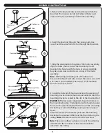
10. Raise the canopy, ensure the two mounting bracket

screws are aligned with the J-shaped slots in the canopy.

Then turn the canopy in a clockwise direction until the

mounting bracket screws are completely engaged in

the J-shaped slots. Install the two previously removed

mounting bracket screws in the round holes. Securely

tighten all mounting bracket screws.

11. Partially insert the blade screws along with the blade

washers through the blade and into the blade arm.

Tighten each blade screw with a Phillips screwdriver (not

included), starting with the one in the middle.

Repeat this step for the remaining blades and blade arms.

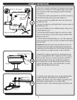
9. Use wire connectors and push-in connectors to connect 

the receiver and fan wires to the supply wires from outlet 

box according to the wiring diagram and the following 

instructions: 
• Connect the Green wires from the fan and the mounting 

bracket to the Bare/Green (ground) supply wire. 
• Connect the Blue wire (FOR LIGHT) from the receiver to 

the Blue fan wire. 
• Connect the Black wire (TO MOTOR L) from the receiver to 

the Black fan wire. 
• Connect the White wire (TO MOTOR N) from the receiver 

to the White fan wire. 
• Push the Black (Hot/Power) supply wire into the empty 

wire hole in push-in wire connector preassembled to the 

Black wire (AC IN L). 
• Push the White (neutral) supply wire into the empty wire 

hole in push-in wire connector preassembled to the White 

wire (AC IN N).

Important:

 After the connections have been made, the 

connected wires should be turned upward and pushed 

carefully up into the outlet box. Place the black and white 

wire connections on opposite sides of the outlet box.

Содержание 42224

Страница 1: ...9689 090120 1 ELMHURST CEILING FAN Owner s Manual Model 42224 Item 2599769 To obtain service please contact the Service Department 1 877 706 3267 8 a m 5 p m Central Monday Friday...

Страница 2: ...de Screw x9 26 Blade Washer x9 27 Wire Connector x4 Unpack your fan and check the contents You should have the following items PACKAGE CONTENTS HARDWARE CONTENTS Note Some extra hardware has been incl...

Страница 3: ...gher For taller ceilings you may want to use a longer downrod not included Angled Ceiling Mount is best suited for angled or vaulted ceilings A longer downrod is sometimes necessary to ensure proper b...

Страница 4: ...mful interference and 2 this device must accept any interference received including interference that may cause undesired operation This equipment has been tested and found to comply with the limits f...

Страница 5: ...all To reduce the risk of fire electric shock or personal injury mount to outlet box marked acceptable for fan support and use mounting screws provided with the outlet box The installation has to be i...

Страница 6: ...box WARNING To reduce the risk of fire electric shock or personal injury mount to the outlet box marked acceptable for fan support and use the mounting screws and washers provided with the outlet box...

Страница 7: ...r For best results stick the antenna to the ceiling Downrod Pin Downrod Clip Yoke Downrod Set Screw 7 Slide the downrod into the yoke of the motor assembly align the holes then re install the downrod...

Страница 8: ...the middle Repeat this step for the remaining blades and blade arms 9 Use wire connectors and push in connectors to connect the receiver and fan wires to the supply wires from outlet box according to...

Страница 9: ...ntil it is secure CAUTION Avoid cross threading the glass during installation Improper installation could cause the glass bowl to be difficult to remove or fall which could cause serious injury 13 Rem...

Страница 10: ...were synced at the factory If the wall control does not operate the fan see TROUBLESHOOTING page 13 16 Loosen all four and completely remove one of the cage screws preassembled to the light pan Then l...

Страница 11: ...ht Control Turns the light on and off Press and hold to dim or brighten lights for dimmable bulbs only High Speed Turns on fan at high speed Light Delay Light stays on for 60 seconds to allow for safe...

Страница 12: ...eiling area Important Wait for the fan to stop before moving the reverse switch The reverse switch must be set either completely left or right in order for the fan to function correctly If the reverse...

Страница 13: ...tate variable speed controls DO NOT USE a Solid State variable speed control 5 Ensure fan does not wobble excessively see Fan wobbles solutions below 1 Ensure the mounting bracket is tightened securel...

Страница 14: ...this warranty HKC assumes no responsibility whatsoever for fan installation Any service performed by a non licensed electrician will render the warranty invalid HKC s sole responsibility shall be to r...

Отзывы: