background image

Please read and understand this entire manual before attempting to assemble, operate or install the 

product. If you have any questions regarding the product, please call customer service at 

1-800-643-0067

, 8 a.m. - 4:30 p.m., EST. 

WARNING:

•  Important: When using an existing outlet box, be sure the box is securely attached to the building 

structure and can support the full weight of the fan. Failure to do so can result in serious injury or 
death.

•  Turn off circuit breakers and wall switch to the fan supply wire leads.  Warning: Failure to 

disconnect power supply prior to installation may result in serious injury or death.

•  Do not install fan on a ceiling with a pitch greater than 20°.
•  Installation work and electrical wiring must be done by qualified person(s) in accordance with all 

applicable codes and standards (ANSI/NFPA 70-1999).  If you are unfamiliar with the wiring 
codes, contact a qualified electrician.

•  Important: Be sure wiring box is properly grounded or that a ground (green) wire is present. 
•  Make sure the installation site you choose allows a minimum of 7 feet from the floor to the end of 

the blades 

PREPARATION

Before beginning assembly of product, make sure all parts are present. Compare parts with package 
contents list and diagram. If any part is missing or damaged, do not attempt to assemble the product. 
Contact customer service for replacement parts.

Estimated assembly time:  30 minutes to 1 hour.

Tools Required for Assembly (not included): Phillips screwdriver, flathead screwdriver, wire strippers, 
electrical tape, ladder, safety glasses, silicone caulk, caulking gun.

SAFETY INFORMATION

ASSEMBLY INSTRUCTIONS

4

•  WARNING-To reduce risk of fire, electric shock, or personal injury, mount to outlet box marked 

“Acceptable for Fan Support of 15.9kg (35lbs) or less” and use mounting screws provided with the 
outlet box and/or support directly from building structure.  Most outlet boxes commonly used for 
the support of luminaries are not acceptable for fan support and may need to be replaced.  
Consult a qualified electrician if in doubt.

•  Warning-Risk of fire, electric shock, or personal injury. Ceiling fans may be either directly 

supported from a structural framing member of a building and (see examples in figures A & B) or 
may be mounted to an outlet box marked acceptable for fan support of 31.8 kg (70 lbs) to 15.9kg 
(35 lbs) (see example in figure C).

Lowes.com/harborbreeze

A

B

C

Содержание 35061

Страница 1: ...an ais p 14 Questions problems missing parts Before returning to your retailer call our customer service department at 1 800 643 0067 8 a m 6 p m EST Monday Thursday 8 a m 5 p m EST Friday ATTACH YOUR...

Страница 2: ...PACKAGE CONTENTS 2 Lowes com harborbreeze A C F R F W F S F T F U F V D B L M P O E G H I N Q K J F...

Страница 3: ...nopy 1 Canopy Hole Cover 1 Motor Coupling Cover 1 Motor Assembly 1 Shade Housing 1 Light Housing 1 Blade Screws 15 Blade 5 Shade 1 Remote 1 Receiver 1 23A Battery 1 Bulb 2 Lag Screw 1 Lag Screw Washer...

Страница 4: ...end of the blades PREPARATION Before beginning assembly of product make sure all parts are present Compare parts with package contents list and diagram If any part is missing or damaged do not attempt...

Страница 5: ...a pitch greater than 20 1 A T U 2 Remove the hairpin B clip and clevis pin C from the downrod support of the motor assembly H and loosen the two set screws Slide the downrod D through the canopy E can...

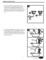
Страница 6: ...hed to the outlet box Be sure the groove in the ball is lined up with the tab on the hanger bracket A 3 4 For Canadian installation and for USA fans over 35 lbs the safety cable must be installed into...

Страница 7: ...This must be done so that your fan will communicate properly If you are using more than one fan in the same area and want to control them separately change one fan s dip switch settings in the transm...

Страница 8: ...an motor wire to BLUE receiver unit wire marked FOR LIGHT Connect BLACK fan motor wire to BLACK receiver unit wire marked TO MOTOR L Connect BLACK supply wire to RED receiver unit wire marked AC IN L...

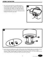
Страница 9: ...outlet box with the white and green wires to one side of the box and the black wire toward the other side 8 Loosen the two shoulder screws without fully removing the hanger bracket A Assemble canopy...

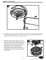
Страница 10: ...talling the shade housing Remove one of the three screw on the mounting plate and loosen the other two Feed the 9 pin connector and safety cable through the center opening of the shade housing I Align...

Страница 11: ...hree screw on the shade housing I and loosen the other two Connect the 9 pin connector from motor assembly and light housing J together The two connectors have keyholes that must be mated correctly be...

Страница 12: ...This remote R has a memory function The remote R stores the fan speed and light setting when the fan is turned off When the fan is turned on again it starts with the most recent setting Use the fan re...

Страница 13: ...ranty Any service performed by an unauthorized person will render the warranty invalid Due to varying climatic conditions this warranty does not cover changes in brass finish rusting pitting tarnishin...

Страница 14: ...ons des probl mes des pi ces manquantes Avant de retourner l article au d taillant appelez notre service la client le au 1 800 643 0067 entre 8 h et 18 h HNE du lundi au jeudi ou entre 8 h et 17 h HNE...

Страница 15: ...CONTENU DE L EMBALLAGE 15 Lowes com harborbreeze A C F D B L M P O E G H I N Q K J F R F S F T F U F V F W...

Страница 16: ...uvercle 1 Couvercle d accouplement du moteur 1 Assemblage de moteur 1 Bo tier d abat jour 1 Bo tier de lumi re 1 Vis de pale 15 Pales 5 Abat jour 1 Contr le distance 1 R cepteur 1 Pile 23A 1 Ampoule 2...

Страница 17: ...nt de commencer l assemblage du produit assurez vous d avoir toutes les pi ces Comparez les pi ces dans l emballage avec la liste et le tableau ci dessus S il y a des pi ces manquantes ou endommag es...

Страница 18: ...20 2 Retirez la pince en pingle cheveux B et l axe paulement C du support de tige de descente de l assemblage du moteur H et desserrez les deux vis de serrage Glissez la tige de descente D par le cou...

Страница 19: ...que la rainure de la sph re s aligne avec la languette sur la fixation suspendue A 3 4 Pour l installation canadienne et pour les ventilateurs des U de plus de 15 8 k 35 lb le c ble de s curit doit tr...

Страница 20: ...r que votre ventilateur communique correctement Si vous utilisez plus d un ventilateur au m me endroit et que vous d sirez les contr ler s par ment changez les r glages du commutateur dip du ventilate...

Страница 21: ...U portant la mention FOR LIGHT POUR L CLAIRAGE Branchez le fil du moteur du ventilateur NOIR au fil du r cepteur NOIR portant la mention TO MOTOR N AU MOTEUR N Branchez le fil d alimentation NOIR au f...

Страница 22: ...blancs et verts d un c t du coffret et le fil noir vers l autre c t 8 Desserrez les deux vis paulement sans retirer compl tement de la fixation suspendue A Assemblez le couvercle E en tournant la fen...

Страница 23: ...bo tier d abat jour Retirez l une des trois vis sur la plaque de montage et desserrez les deux autres Acheminez le connecteur 9 broches et le c ble de s curit par l ouverture centrale du bo tier d aba...

Страница 24: ...trois vis sur le bo tier d abat jour I et desserrez les deux autres Branchez le connecteur 9 broches de l assemblage de moteur et du bo tier de lumi re J ensemble Les deux connecteurs ont des trous d...

Страница 25: ...outon soit d gag La lumi re conservera le dernier r glage si on l teint Ce contr le distance R a une fonction de m moire Le contr le distance R m morise la vitesse du ventilateur et le r glage d clair...

Страница 26: ...ctueuses pour le ventilateur de plafond doit tre rapport dans la premi re ann e de la date d achat Pour le reste de la garantie appelez notre service la client le pour l autorisation de retour et les...

Отзывы: