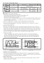
HANYOUNG NUX NP100 Скачать руководство пользователя страница 20

21

【 Fuzzy Function 】

PV

Target SV

Subsidiary target SV

PV

Start FUZZYreasoning

Time

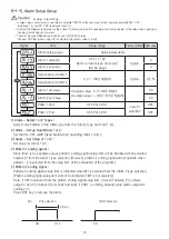
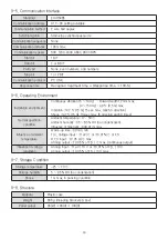
8-1-6.     Control Setup Group

Signal

Item

Setup range

Display condition Initial value

Control setup group

Setup below items.

Fuzzy function 
selection

OFF/ON

Except

ON / OFF

OFF

Time unit selection

HH.MM (00 hr. 00 min.)

MM.SS  (00 min  00 sec.)

Always

HH.MM

Wait zone setup

OFF/0~max. range

OFF

Wait time setup

OFF / 0.01~99.59

OFF

Power recovery
motion mode

COOL / HOT

COOL

1) Selection of Fuzzy Function :


  Fuzzy function is an over shoot inhibitory function using the fuzzy reasoning. Fuzzy function can provide 
  control effects in the following situations
· Starting the control when there are variation between the desired set value and actual process value
· Wanting to reduce the operative preheating period
· Having severe load changes  
· Having frequent changes to set value

2) Selection of Time Unit :


  Maximum of 99 hours 59 minutes or 99 minutes 59 seconds can be selected in the setup item for the 
  selection of time unit.

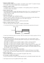
3) Setup of Wait Zone :


  Process value must agree in accord to the process of programmed set value in program temperature   
  controller but unpredicted events occur. Here, if the temperature variation set in the wait zone when 
  moving segments, program can continue on to the next segment.  However, if it is outside the 
  variation range, it doesn’t move on from the current segment to the next segment but rather waits until it   
  enters the set range of wait zone.

4) Setup of Wait Time :


  When the process value doesn’t agree with the progress of the programmed set value in the 
  program temperature controller, in other words, when the process value is not controlled within the range 
  of set variation between the set value + the wait zone, program continues on when the wait time elapses. 

5) Power Recovery Motion Mode : 

  Can choose between COOL or HOT in the set up item.  If COOL is selected, the system resets when 
  recovered from the power failure and if HOT is selected, it continues on from the segment operated just 
  before the failure.

 ※ However, must start from the beginning of the segment even if the system recovers to the segment just 
     operated before the power failure. 

Содержание NP100

Страница 1: ...Manual NP100 Programmable Controller...

Страница 2: ...IMENSION PANEL CUTOUT 5 INPUT OUTPUT Input Signal and Measurement Range Output type 6 NAME FUNCTION 7 LIST OF SETUP ITEMS 8 SETUP METHOD Program Setup 9 SPECIFICATION Input Function 10 ALARM TYPE CODE...

Страница 3: ...essive induction trouble static electricity or magnetic noise 1 If there is a possibility of an accident caused by errors or malfunctions of this product install external protection circuit to prevent...

Страница 4: ...of operation is rather high In this case SSR output type is recommended Electromagnetic switch Proportional cycle time is Min 20 sec SSR Proportional cycle time is Min 1 sec Contact output life Mechan...

Страница 5: ...d each segment s parameter Feature Function Description Option RS 485 422 Time signal 2 points PV display Digit number 4 digits Accuracy 0 1 Sampling time 250 ms Input type Universal input selectable...

Страница 6: ...tion ground wiring Ground connection cable is a thick wire that is over 2 in width Wire with more than the third type ground connection below 100 ground connection resistance The length of the ground...

Страница 7: ...1 199 9 999 9 T 1 199 9 400 0 R 0 1700 0 15 of F S 1digit B 2 0 1800 S 0 1700 L 1 199 9 900 0 0 1 of F S 1digit N 200 1300 0 2 of F S 1digit U 1 199 9 400 0 0 1 of F S 1digit W 0 2300 Platinel 0 1390...

Страница 8: ...when WAIT is in operation while the program is running on HOLD display lamp Lights when HOLD is in operation while the program is running on MAN display lamp Lights while manually operating AL1 displa...

Страница 9: ...the parameter Press 2 5 seconds or longer to alternate the operation indicator mode and the engineering mode Exit running program and convert to stop Exit runing MAN operation and convert to reset mod...

Страница 10: ...when the button is pressed continuously Rounding Off 4 Maximum Minimum Indication It indicates the greatest or the least of the selected item when it gets out of the range of the selected item parame...

Страница 11: ...indicated in running Operation indicator mode Engineering mode Power ON Process value Set value Process value Output value Display remain time of segment 2 5 sec or PID OFF Displayed in running condit...

Страница 12: ...Mode setup is recommended after completing the Program operation since the set value varies in accordance with the setup of the specific parameter Each parameter may not be indicated in accordance wi...

Страница 13: ...ss value Output value Display remain time of segment Operation indicator mode PT NO n PT NO 0 We recommend you to use program mode after engineering mode is closed A set up value is changed and initia...

Страница 14: ...ch segment s parameter Power ON Press 2 5 second Engineering group Program group 1 Input setup group 8 1 1 8 1 2 8 1 3 8 1 4 8 1 5 8 1 6 8 1 7 8 1 8 2 Output setup group 3 Communication setup group 4...

Страница 15: ...to compensate voltage for the terminal temperature Otherwise it will show declination as much as the terminal temperature surrounding temperature 6 Selection of Process Value Filter When instability o...

Страница 16: ...the control output 5 Preset Output Volume This is useful when preheating condition must be maintained through continuous output volume previously set up by disconnecting the output from the PID calcu...

Страница 17: ...PCL 1 PC LINK SUM Option PCL 0 Communication rate BAUD RATE 600 1200 2400 4800 9600 bps 9600 PARITY NONE EVEN ODD NONE STOP BIT 1 or 2 bit 1 DATA LENGTH 7 or 8 except PC Link 8 8 ADDRESS 1 99 max 31...

Страница 18: ...utput When using the retransmission output it is impossible to use the SPS function for sensor SPS Output Wiring for Sensor Must disconnect the controller and external power source when setting up rem...

Страница 19: ...Alarm 2 set value 0 0 Patter 1 End OFF PUL CONT code 21 selection OFF Patter 2 End OFF PUL CONT OFF 1 Alarm Select 1 or 2 Types Select code number of the Alarm type from the Alarm Type and Code list...

Страница 20: ...ion of time unit 3 Setup of Wait Zone Process value must agree in accord to the process of programmed set value in program temperature controller but unpredicted events occur Here if the temperature v...

Страница 21: ...the PID group in agreement with the selected number from the auto tuning selection in the auto tuning setup group is applied to each pattern segment of 4 types due to the selection of pattern segment...

Страница 22: ...the 10 of the set value The symbol for the auto tuning setup group is only indicated in operative period The auto tuning output is not indicated if ON OFF has been already selected 1 Selection of Aut...

Страница 23: ...ss for 2 5 seconds Engineering group Program groupt Repeat time setup 1 Pattern has been assigned See page 24 of 0 segment parameter of program setup Set up segment number 1 See 1 segment parameter Se...

Страница 24: ...p items Repeat frequency setup 0 limitless frequency 1 99 Always 1 Setup group for program repeat frequency is indicated if the system is operated as follow when power is ON Power ON 2 5 sec 1 Set up...

Страница 25: ...ime signal 1 ON time OFF 00 00 99 59 Segment 0 OFF Setup of n pattern time signal 1 OFF time OFF 00 00 99 59 ON time OFF time Segment 0 OFF Setup of n pattern time signal 2 ON time OFF 00 00 99 59 Seg...

Страница 26: ...pattern 6 Setup of n pattern time signal 1 OFF time It turns OFF after the set time of time signal 1 of already selected pattern 7 Program Completion Mode When pattern 1 is selected as mode upon the c...

Страница 27: ...nge Input resistance Thermocouple mV input 1 M min V DC input Approx 1 M Allowable signal source resistance Thermocouple max 250 mV V DC input max 2 K Allowable wiring resistance RTD input max 10 1 wi...

Страница 28: ...solution 0 1 or 10 ms Current output SCR output 4 20 A DC Current output range 4 20 mA DC Resistive load 600 max Accuracy 0 3 of full scale 4 20 mA range Resolution Approx 3 000 Output ripple 0 1 P P...

Страница 29: ...ontinuous vibration 5 14 Hz Forward width 1 2 mm max 4 150 Hz 4 9 0 5 G max Vibration 14 7 1 5 G 15 sec max each 3 direction Shock 147 15 G 11msec max 6 direction each 3 times Normal operation conditi...

Страница 30: ...on Resistance Primary terminal Secondary terminal MIN 500 V DC 20 M Primary terminal Ground MIN 500 V DC 20 M Ground Secondary terminal MIN 500 V DC 20 M 9 11 Dielectric strength Primary terminal Seco...

Страница 31: ...action Select Direct or Reverse action in output group Emergency Preset 0 5 105 0 of output value ON OFF Hysteresis 0 0 100 0 of range When selecting ON OFF control follow the HYS set up of output gro...

Страница 32: ...d alarm 8 18 DEV ALM DEV ALM DEV ALM HYS DEV ALM HYS High absolute alarm inverted 9 19 PV ALM PV ALM HYS Low absolute alarm inverted 10 20 PV ALM PV ALM HYS Pattern ending signal 21 Pattern ending sig...

Страница 33: ...rm 8 High Low band 9 High absolute inverted 10 Low absolute inverted 11 High absolute with hold function 12 Low absolute with hold function 13 High deviation with hold function 14 Low deviation with h...

Страница 34: ...he introduction manual please refer to a sign which is displayed as FND is marked as following English characters for some reason Alphabet FND Alphabet FND Alphabet FND A N 1 B O 2 C P 3 D Q 4 E R 5 F...

Страница 35: ...ime 8 1 8 Auto tuning AT type AT operation 8 2 1 Program repeat frequency Frequency 8 1 7 PID setup group ARW P I D Manual reset Group 1 Group 2 Group 3 Group 4 Segment Mode 1 2 3 4 5 6 7 8 9 10 Patte...

Страница 36: ...HANYOUNG NUX CO LTD 28 Gilpa ro 71 beon gil Nam gu Incheon Korea TEL 82 32 876 4697 FAX 82 32 876 4696 http www hynux com E mail overseas hynux com MA0102E140110...

Отзывы: