


24_
flush mount dome camera
flush mount dome camera
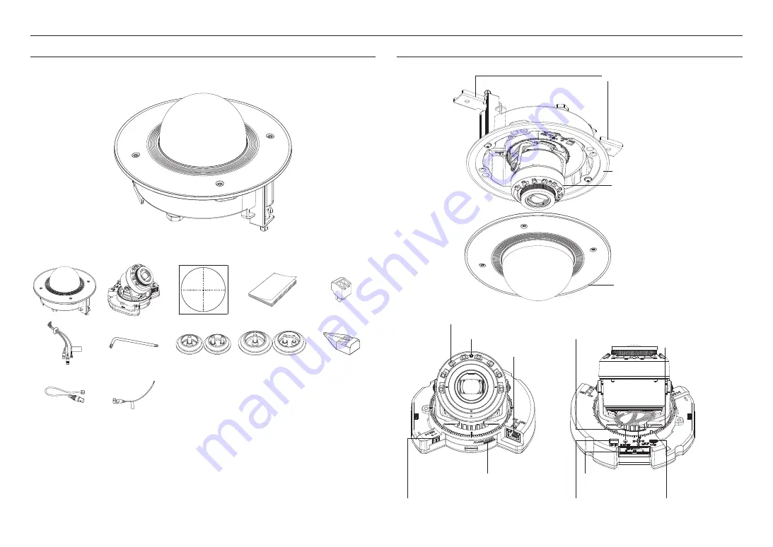
WHAT’S INCLUDED
As for each sales country, accessories are not the same.
<XND-9082RF/XND-8082RF>
C
AU
TIO
N
: B
e w
are
o
f th
e
R
ate
d V
olt
ag
e a
nd
P
ola
rity
of
th
e p
ow
er
co
nn
ec
tio
n.
C
AU
TIO
N
: B
e w
are
o
f th
e
R
ate
d V
olt
ag
e a
nd
P
ola
rity
of
th
e p
ow
er
co
nn
ec
tio
n.
C
AU
TIO
N
: B
e w
are
o
f th
e
R
ate
d V
olt
ag
e a
nd
P
ola
rity
of
th
e p
ow
er
co
nn
ec
tio
n.
C
AU
TIO
N
: B
e w
are
o
f th
e
R
ate
d V
olt
ag
e a
nd
P
ola
rity
of
th
e p
ow
er
co
nn
ec
tio
n.
C
AU
TIO
N
: B
e w
are
o
f th
e
R
ate
d V
olt
ag
e a
nd
P
ola
rity
of
th
e p
ow
er
co
nn
ec
tio
n.
C
AU
TIO
N
: B
e w
are
o
f th
e
R
ate
d V
olt
ag
e a
nd
P
ola
rity
of
th
e p
ow
er
co
nn
ec
tio
n.
AT A GLANCE
Bracket
a
Housing
b
Camera-module
c
Dome-cover
d
f
IR LED
g
Illumination Sensor
k
Power port
(DC 12 V)
l
Audio/Alarm cable
port
h
Network
port
i
Reset button
j
Zoom/Focus
Control Button
o
Micro USB port
n
Micro SD card slot
m
Test monitor out port
flush mount dome camera
Содержание Wisenet XNV-9082R
Страница 56: ......


