overview
12_
overview
AT A GLANCE
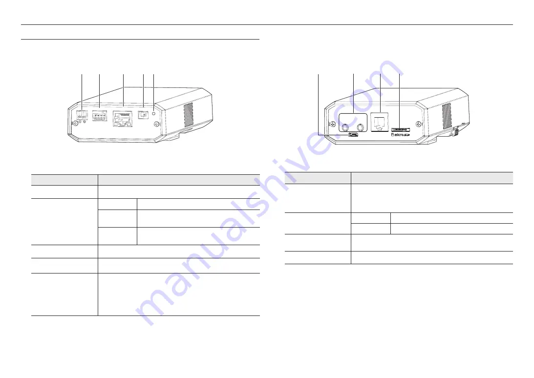
Front of the main unit
a
b
c
d e
4 3 2 1
DC 12V
NETWORK
VIDEO
RESET
GND : 1, 2
ALARM OUT : 3
ALARM IN : 4
AUDIO
OUT
AUDIO
IN
USB
CAM
Item
Description
a
Power Port(DC 12V)
Port for power terminal block.
b
Alarm I/O Port
GND
Ground terminal.
ALARM OUT
The terminal sends the alarm output signal.
Refer to “Alarm Out Wiring Diagram” (page 21).
ALARM IN
The terminal sends the alarm input signal.
Refer to “Alarm In Wiring Diagram” (page 21).
c
Network Port
Terminal used to connect to PoE or LAN via the RJ-45 cable.
d
Test monitor out port
Output port for test monitoring the video output. Use the test monitor cable to connect to a
mobile display and check the test video.
e
Reset Button
The button restores all camera settings to the factory default.
Press and hold for about 5 seconds to reboot the system.
J
If you reset the camera, the network settings will be adjusted so that DHCP can be
enabled. If there is no DHCP server in the network, you must run the Device Manager
program to change the basic network settings such as IP address, Subnet mask,
Gateway, etc., before you can connect to the network.
Rear of the main unit
4 3 2 1
DC 12V
NETWORK
VIDEO
RESET
GND : 1, 2
ALARM OUT : 3
ALARM IN : 4
AUDIO
OUT
AUDIO
IN
USB
CAM
b
a
c
d
Item
Description
a
MICRO USB port
Port to connect the Wi-Fi dongle.
You can check the installation video through the applications installed in the smartphone.
Refer to “
Connecting WiFi
” on page 20.
`
Wifi dongle and OTG adapter are sold separately.
b
Audio cable port
AUDIO IN
Used to connect to a microphone.
AUDIO OUT
Used to connect to speakers.
c
Connection terminal of lens
module
This terminal is connected to the lens module through the cable to connect the lens
module.
d
Micro SD Card slot
Compartment for the Micro SD card.
Содержание Wisenet XNB-6002
Страница 31: ......


