background image


User Manual                                                                                                                                                                          61 

"Negative". The default is "Positive". 


Manual Trigger: 

A sweep will be generated from the corresponding channel once you press 

Trigger 

at the front panel. 


6.10 Trigger Output Edge 

In sweep mode, when "Internal" or "Manual" trigger source is selected, the generator will output a 

TTL compatible signal with specified edge from the 

[Sync/Mod/Trig] 

connector at the front panel. 


Internal and Manual Trigger

: The generator outputs a Pulse waveform from the 

[Sync/Mod/Trig] 

connector at the beginning of the Sweep. The trigger period depends on the specified sweep time, 

return time and hold time. The pulse waveform changes from high-level to low-level at the 

specified mark frequency point or greater than the mark frequency.   

External Trigger

: The 

[Sync/Mod/Trig] 

connector is used as the input terminal of external trigger 

signal and has no trigger output.   


Содержание HDG2000B Series

Страница 1: ...HDG2000B series Functions and Arbitrary Waveform Generator User manual V1 2...

Страница 2: ...t the channel 15 2 2 Setting the parameter 15 2 2 1 Select the Basic Waveform 15 2 2 2 Set the Frequency 15 2 2 3 Set the Amplitude 16 2 2 4 Set the DC Offset Voltage 16 2 2 5 Set the Start Phase 17 2...

Страница 3: ...3 1 Select FM Modulation 36 5 3 2 Carrier Waveform Shape 37 5 3 3 Carrier Frequency 37 5 3 4 Modulating Waveform Source 37 5 3 5 Modulating Waveform Frequency 38 5 3 6 Frequency Deviation 38 5 4 PM Mo...

Страница 4: ...5 9 4 Modulating Waveform Source 48 5 9 5 QPSK Rate 49 5 9 6 Modulating Phase 49 5 10 3FSK Modulation 49 5 10 1 Select 3FSK Modulation 49 5 10 2 Carrier Waveform Shape 49 5 10 3 Carrier Frequency 49 5...

Страница 5: ...Source 60 6 10 Trigger Output Edge 61 Chapter 7 Burst 62 7 1 Select Burst Mode 63 7 2 Burst Type 63 7 3 Burst Period 65 7 4 Burst Phase 65 7 5 Burst Trigger Source 65 7 6 Gate Polarity 66 7 7 Trigger...

Страница 6: ...tem Information 79 10 4 6 Clock Source 79 10 5 Print 80 10 6 Update 80 Chapter 11 Remote Control 81 11 1 Install Keysight IO libraries suite 82 11 2 Remote Control via USB 86 Appendix A Specifications...

Страница 7: ...Hantek Hantek reserves all rights to modify this document without prior notice Please contact Hantek for the latest version of this document before placing an order Hantek has made every effort to ens...

Страница 8: ...ng conductor must be connected to earth ground Before making connections to the input or output terminals of the product ensure that the product is properly grounded Connect the probe in a right way T...

Страница 9: ...operties if you perform the operation Characters on the product The following characters may appear on the product Product Scrapping Device Recycling We need extract and utilize natural resources to p...

Страница 10: ...Support frequency sweep and Burst output Dual channels can perform internal external another channel modulation and internal external manual trigger separately or at the same time Dual channels can o...

Страница 11: ...User Manual 5 Models Model Channels Bandwidth Sample Rate HDG2102B 2 100MHz 500MS s HDG2082B 2 80MHz 500MS s HDG2062B 2 60MHz 500MS s HDG2032B 2 30MHz 500MS s...

Страница 12: ...s the front panel rear panel user interface and parameter setting method as well as precautions when using the instrument for the first time General Inspection Front Panel Rear Panel Prepare Instrumen...

Страница 13: ...damaged please notify the franchiser Check the instrument In case there is any mechanical damage or defect or the instrument does not operate properly or fails performance tests please notify the fra...

Страница 14: ...e and 1K nominal input impedance Its function is determined by the current working mode of CH1 Mod If modulation mode is enabled for CH1 and external modulation source is used this connector accepts a...

Страница 15: ...Operation key Print It is used to execute the print function to save the content displayed on the screen as image in USB storage device Store Users can store or recall the instrument state Provide a...

Страница 16: ...for stable placement of the oscilloscope as well as better operation and observation Connect the Power Cord Connect the power cord as desired This oscilloscope can accept 100 240 V 45 440 Hz AC power...

Страница 17: ...HighZ 50 Impedance is 50 Mode Modulation display Mod Sweep display Sweep Burst display Burst Continuous output display Conti ON OFF state Channel output ON or OFF 2 Status Bar The following indicators...

Страница 18: ...ndicates current cursor location 7 Waveform Display the currently selected waveform shape in each channel 8 Counter The brief information of the counter will only be displayed when the frequency count...

Страница 19: ...to move the cursor Functions of the knob When the parameter is in editable state turn the knob to increase clockwise or reduce counterclockwise the parameter with specified step During filename edit...

Страница 20: ...he channels separately or from the two channels at the same time At start up the channel is configured as a sine waveform with 1KHz frequency and 200mVpp amplitude by default This chapter introduces h...

Страница 21: ...f the button turns on The waveform type and the parameter setting menu are displayed on the right of the user interface 2 2 2 Set the Frequency Press Frequency Period softkey to highlight Frequency At...

Страница 22: ...ngs Please refer to Output Characteristics in Specifications The default value is 200mVpp Tips Switch between Vpp and Vrms Vpp is the unit for the signal peak peak value and Vrms is the unit for the s...

Страница 23: ...the direction keys and knob to modify the current value For the input method of phase value refer to the introduction in Parameter Setting Method 2 2 6 Align Phase Press Align Phase and the instrument...

Страница 24: ...up unit menu or use the direction keys and knob to modify the current value For the input method of duty cycle value refer to the introduction in Parameter Setting Method The duty cycle range is limit...

Страница 25: ...in addition to the basic parameters such as the frequency amplitude DC offset voltage high level low level and align phase introduced above Pulse Width Duty Cycle Pulse width is defined as the time fr...

Страница 26: ...ure above The range of the leading trailing edge time is limited by the pulse width currently specified as shown in the formula below The edge time will be automatically adjusted to match the specifie...

Страница 27: ...ress Offset LoLevel to highlight Offset Use the numeric keyboard to input the offset value 5 and select the unit mV from the pop up menu 6 Press Width Duty to highlight Width Use the numeric keyboard...

Страница 28: ...The 160 kinds of built in waveforms are stored in the internal non volatile memory The user defined arbitrary waveforms can contain 64 to 64M data points Users can edit the arbitrary waveforms via the...

Страница 29: ...e softkey to select the instrument built in waveform output Select more than 160 kinds of arbitrary waveform built in HDG2000B as shown in the following table Press type select a type Math Project Dis...

Страница 30: ...veform StepResp Step response signal SwingOsc Kinetic energy time curve of swing oscillation TV TV signal Voice Voice signal Sec Mod AM Sectioned sine AM signal FM Sectioned sine FM signal PFM Section...

Страница 31: ...function Cauchy Cauchy distribution function Cubic Cubic function Dirichlet Dirichlet function Erf Error function Erfc Complementary error function ErfcInv Inverted complementary error function ErfIn...

Страница 32: ...cave arc hyperbolic cotangent ACotHPro Protuberant arc hyperbolic cotangent ACscCon Concave arc cosecant ACscPro Protuberant arc cosecant ACscHCon Concave arc hyperbolic cosecant ACscHPro Protuberant...

Страница 33: ...red in external memory U Disk Press Store softkey to enter the Store Recall Interface Please select and read the desired arbitrary waveform file For more details please refer to Store and Recall To re...

Страница 34: ...phase It is usually used in the test of harmonic detector device or harmonic filter device This chapter introduces how to configure the generator to output harmonics Subjects in this chapter Overview...

Страница 35: ...d phase of each order of harmonic After finishing harmonic parameter setting press Output1 or and Output2 and the backlight of the button turns on the instrument outputs the specified harmonic from th...

Страница 36: ...y to select the sequence number of the harmonic to be set 2 Amplitude press this softkey to set the amplitude of the harmonic selected Use the numeric keyboard to input the amplitude value and then se...

Страница 37: ...form consists of carrier waveform and modulating waveform The carrier waveform can be Sine Square Ramp Pulse Arbitrary waveform except DC or Harmonic The modulating waveform can be from internal defau...

Страница 38: ...except DC or Harmonic waveform Press the front panel key Sine Square Ramp Pulse Arb Type or Harmonic to select a desired carrier waveform shape Noise and DC could not be used as carrier waveform 5 1...

Страница 39: ...annel Other channel CH1 and CH2 can be used as modulation sources reciprocally When CH1 is used as the modulated wave CH2 can be used as the modulation source And vice versa 5 1 5 Modulating Waveform...

Страница 40: ...ier component Its frequency bandwidth is still twice the frequency of the modulated signal 5 2 1 Select DSB AM Modulation Press Mod Type DSB AM to enable DSB AM function When Mod is enabled Sweep or B...

Страница 41: ...rnal modulation source is selected press Shape to select Sine Square Ramp Noise or Arb as modulating waveform The default is Sine Sine waveform Square 50 duty cycle Ramp 50 symmetry Note Noise can be...

Страница 42: ...ed value In 100 modulation the output amplitude of the instrument would not exceed 10Vpp 50 load When Ext modulation source is selected the output amplitude of the instrument is also controlled by the...

Страница 43: ...ed you can press Frequency Period to highlight Frequency and then use the numeric keyboard or direction keys and knob to input the desired frequency value 5 3 4 Modulating Waveform Source HDG2000B can...

Страница 44: ...selected 5 3 6 Frequency Deviation Frequency deviation is the deviation of the modulating waveform frequency relative to the carrier frequency Press Deviation to set the FM frequency deviation Frequen...

Страница 45: ...rms To avoid multiple waveform changes enable modulation after configuring the other modulation parameters 5 4 2 Carrier Waveform Shape PM carrier shape Sine default Square Ramp Pulse Arbitrary except...

Страница 46: ...the carrier waveform The Phase Deviation is controlled by the 2 5 V signal level on the front panel Sync Mod Trig connector Other Channel Other channel CH1 and CH2 can be used as modulation sources re...

Страница 47: ...tude is determined by the internal signal level of the instrument or the signal level on the front panel Sync Mod Trig connector 5 5 1 Select 2ASK Modulation Press Mod Type 2ASK to enable this functio...

Страница 48: ...lating signal from the Sync Mod Trig connector at the pront panel Note The Sync Mod Trig connector is different when controlling 2ASK and AM FM PM modulations externally In 2ASK modulation the Sync Mo...

Страница 49: ...the instrument will generate 2FSK waveform with the currently specified carrier and modulating waveforms To avoid multiple waveform changes enable modulation after configuring the other modulation par...

Страница 50: ...is different when controlling 2FSK and AM FM PM modulations externally In 2FSK modulation the Sync Mod Trig connector has adjustable edge polarity 5 6 5 2FSK Rate When internal modulation source is se...

Страница 51: ...enable this function When Mod is enabled Sweep or Burst will be disabled automatically After 2PSK is enabled the instrument will generate 2PSK waveform with the currently specified carrier and modulat...

Страница 52: ...or is different when controlling 2PSK and AM FM PM modulations externally In 2PSK modulation the Sync Mod Trig connector has adjustable edge polarity 5 7 5 2PSK Rate When internal modulation source is...

Страница 53: ...ape BPSK carrier shape Sine default Square Ramp Pulse Arbitrary except DC or Harmonic waveform Press the front panel key Sine Square Ramp Pulse Arb Type or Harmonic to select a desired carrier wavefor...

Страница 54: ...SK is enabled the instrument will generate QPSK waveform with the currently specified carrier and modulating waveforms To avoid multiple waveform changes enable modulation after configuring the other...

Страница 55: ...hop frequencies is determined by the internal signal level of the instrument or the signal level on the front panel Sync Mod Trig connector 5 10 1 Select 3FSK Modulation Press Mod Type 3FSK to enable...

Страница 56: ...range is from 2mHz to 1MHz and the default is 100Hz 5 10 6 Hopping Frequency Alternating frequency hopping frequency is the modulating frequency The range of hop frequency depends on the carrier wavef...

Страница 57: ...keyboard or direction keys and knob to input the desired frequency Different carrier waveforms have different frequency ranges as shown in the table below For all the carrier waveforms the default va...

Страница 58: ...OSK rate is 10kHz The start oscillation and stop oscillation of the internal crystal oscillator are controlled by the internal signal level or signal level at the Mod FSK Trig connector at the frount...

Страница 59: ...e When internal modulation source is selected the modulating waveform is set as a Square with 50 duty cycle and the intermittence time and oscillate time of the output signal is determined by the OSK...

Страница 60: ...unavailable When Mod is enabled Sweep or Burst will be automatically disabled if enabled currently After PWM is enabled the instrument will generate PWM waveform with the currently specified carrier a...

Страница 61: ...waveform Use the numeric keyboard or direction keys and knob to input the desired frequency value The frequency range is from 2mHz to 50KHz and the default is 100Hz Note This menu will be grayed out...

Страница 62: ...User Manual 56 the Sync Mod Trig connector at the front panel...

Страница 63: ...gure the instrument to output one sweep from start frequency to stop frequency by applying an external or manual trigger The instrument can sweep sine square pulse ramp Harmonic or arbitrary waveforms...

Страница 64: ...rom high frequency to low frequency Start Frequency Stop Frequency the generator outputs with a fixed frequency When frequency sweep is enabled press Start Center to highlight Start Use the numeric ke...

Страница 65: ...0MHz and Fm is about 500MHz If the center frequency is 550Hz the range of the frequency span is 2 550Hz 1 Hz 1 099999998kHz if the center frequency is 90MHz the range of the frequency span range is 2...

Страница 66: ...equency It will output low level when the frequency is less than the mark frequency When Sweep is enabled press Tag Freq use the numeric keyboard or the direction keys and knob to modify the mark freq...

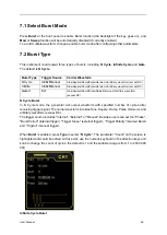
Страница 67: ...from the Sync Mod Trig connector at the front panel Internal and Manual Trigger The generator outputs a Pulse waveform from the Sync Mod Trig connector at the beginning of the Sweep The trigger perio...

Страница 68: ...external or manual trigger source supports three kinds of burst types including N cycle Infinite cycle and Gated Burst is allowed with sine square ramp pulse Harmonic noise allowed only in gated burs...

Страница 69: ...m except DC Gated Ext Sine Square Ramp Pulse Noise Harmonic Arbitrary waveform except DC N Cycle Burst In N Cycle mode the generator will output waveform with specified number of cycles after receivin...

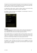
Страница 70: ...o the external signal level from the Sync Mod Trig connector at the front panel The carrier waveform includes Sine Square Ramp Pulse Noise Harmonic and arbitrary waveforms except DC When the gated sig...

Страница 71: ...to input the desired period value The default is 10ms and the settable range is from 2 s to 500s 7 4 Burst Phase Burst phase is defined as the phase of the start point of the burst When Burst is enabl...

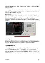
Страница 72: ...L pulse with specified polarity To set the TTL pulse polarity press Slope to select Positive or Negative and the default setting is Positive Manual Trigger When manual trigger is selected the generato...

Страница 73: ...or outputs a square waveform with variable duty cycle related to the carrier period and number of cycles from the Sync Mod Trig connector at the start of burst The trigger period is the same with the...

Страница 74: ...8 Counter The instrument provides a counter which can measure various parameters such as frequency period duty cycle positive pulse width and negative pulse width of external input signal Enable the C...

Страница 75: ...witch to the counter interface The CH1 sync output will be disabled when the counter is enabled 8 2 Set the Counter Gate time Set the gate time of the measurement system Press Gate time and use the di...

Страница 76: ...erator The instrument provides a digital generator which can output the digital signal by sync or programmable The dual channels can still output normally when the digital generator is enabled Termina...

Страница 77: ...al source to CH1 or CH2 3 Open CH1 waveform output Select the Signal Type to Sine frequency to 1KHz Amplitude to 1V Y Offset to 0V 4 Connect Digital Generator Terminals to LOGIC Analyzer Terminals to...

Страница 78: ...User Manual 72...

Страница 79: ...l 73 Chapter 10 Utility The instrumemt allows users to configure the parameters of dual channels configure remote interfaces and set system parameters Sync Impedance Store and Recall System Setting Pr...

Страница 80: ...harmonics sync signal is a square with variable duty cycle and takes the harmonic order as reference For AM DSB AM FM PM and PWM in internal modulation mode the sync signal is a Square with 50 duty cy...

Страница 81: ...e to 10Vpp If the output impedance is changed from HighZ to 50 the amplitude will reduce to half of the previous value 2 5Vpp Note Only the displayed values change with the parameter and the real outp...

Страница 82: ...se the knob to switch between Home Disk and USB Disk when USB storage device is inserted File when this type is selected use the knob to switch files or folders under the current directory Note when t...

Страница 83: ...oftkey to remove the characters in front of the cursor one by one 4 Press Delete softkey to delete all the characters in the Filename Input Area 5 Press Save softkey to save this file 6 Press Return s...

Страница 84: ...folder following the introduction in New File 10 4 System Setting 10 4 1 Set the System Language HDG2000B supports menus in Chinese and English as well as provides corresponding help information promp...

Страница 85: ...onnector at the front panel It can also output the internal clock source from the 10MHz In Out connector for other devices Press Utility Clock Source to select Internal or External The default is Inte...

Страница 86: ...rnal respectively Finally set the output frequencies of all the generators as a same value to realize the synchronization among multi instruments 10 5 Print Users could store the contents displayed on...

Страница 87: ...ut the commands and programming refer to the SCPI protocol manual Use PC software Users can use the PC software to send commands to remotely control the instrument You can download the software from o...

Страница 88: ...suite from CD disk or open the following websit to download latest one http www keysight com main software jspx ckey 2175637 id 2175637 nid 11143 0 00 l c eng cc GB Double click the icon to start inst...

Страница 89: ...User Manual 83 Select a Typical and click Next to continue Or select a Custom and click Next to continue...

Страница 90: ...User Manual 84 Select Install Keysight VISA as primary VISA and click Next to continue Click Install to start copying files...

Страница 91: ...User Manual 85 The installation is completed automatically You will see the running IO program in the lower right corner of the screen...

Страница 92: ...cted to the PC You can also click Rescan to search for the resources 3 View the device resource The resource found will appear under the directory and the model number and USB interface information of...

Страница 93: ...0MSa s Voltage Resolution 16Bit Digital Output 16 Channels output Waveforms Standard Waveforms Sine Square Ramp Pulse Noise Harmonics Arbitrary Waveforms More than 160 kinds including Sinc Exponential...

Страница 94: ...0 fixed Non symmetry 1 of period 5ns Jitter rms Typical 1MHz 1Vpp 50 5MHz 2ppm 500ps 5MHz 500ps Ramp Linearity 1 of peak output 1KHz 1Vpp Symmetry 0 100 Pluse Period 67ns 1Ms 67ns 1Ms 67ns 1Ms 67ns 1...

Страница 95: ...0 1dB 60MHz 0 2dB 1MHz 0 1dB 30MHz 0 2dB Units Vpp mVpp Vrms dBm Resolution 1mV Impedance 50 Offset Characteristic 50 Range Voltset Vmax Vpp 2 Accuracy 1 of setting 5mV 0 5 of amplitude Modulation Cha...

Страница 96: ...ier Waveforms Sine Square Ramp Pluse Harmonics Arb except DC Source Internal External Modulating Waveforms Square with 50 duty cycle Rate 2mHz 1MHz 2FSK Carrier Waveforms Sine Square Ramp Pluse Harmon...

Страница 97: ...e 2mHz 1MHz 4FSK Carrier Waveforms Sine Square Ramp Pluse Harmonics Arb except DC Source Internal Modulating Waveforms Square Rate 2mHz 1MHz OSK Carrier Waveforms Sine Source Internal External OscTime...

Страница 98: ...mHz to 60MHz 2mHz to 30MHz Burst Count 1 to 2000 000 000 Start Stop Phase 0 to 360 Internal Period 2 s to 500s Gated Source External trigger Trigger Source Internal External or Manual Counter Function...

Страница 99: ...Clock Reference External Reference Input Lock Range 10MHz 50Hz Level 2 5Vpp to 5Vpp Lock Time 2s Impedance Typical 5k AC coupling Internal Reference Output Frequency 10MHz 50Hz Level 3 3Vpp Impedance...

Страница 100: ...o operating 15000 meters Mechanical Dimension 318 x 110 x 150mm L x W x H Weight 3KG Appendix B Accessories All the following accessories are available by contacting your local HANTEK distributor Stan...

Отзывы: