
DPO6000, MPO6000 Series Digital Fluorescent Oscilloscope Product Manual V1.3
47
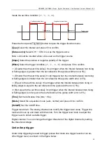
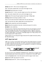
[Holdoff]
Set the holdoff time.
Trigger level knob: You can modify the trigger level value. Trigger the mark and move
up and down with the knob. Turn the trigger level knob to adjust the trigger level to ob-
tain a stable trigger.
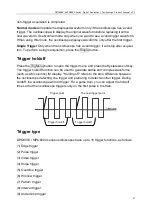
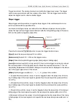
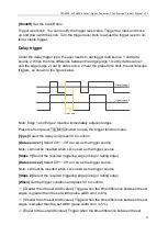
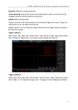
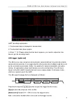
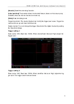
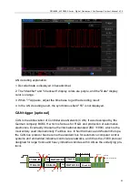
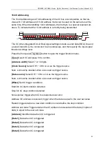
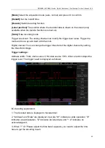
Delay trigger
Under the delay trigger type, the user needs to set trigger data source 1 and data
source 2. When the time difference between the edge (edge 1) set by data source 1
and the edge (edge 2) set by data source 2 meet the preset time limit, the oscilloscope
triggers, as shown in the figure below.
Signal source 1
Delay time
Signal source 2
Note: Edge 1 and Edge 2 must be immediately adjacent edges.
Press the front panel Trig Menu button to open the trigger function menu.
[Type]
Select the delay and press V0 to confirm.
[Data source 1]
Select CH1
~
CH4 or LA as the trigger source.
Note: LA must be inserted when LA is used as the trigger source.
[Slope 1]
Select the required triggering edge (rising or falling edge)
[Data source 2]
Select CH1
~
CH4 or LA as the trigger source.
Note: LA must be inserted when LA is used as the trigger source.
[Slope 2]
Select the required triggering edge (rising or falling edge)
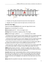
[When]
Set the trigger condition and press V0 to confirm.
>
[Greater than the set width value]: Trigger when the time difference between the set
edges is greater than the set width (pulse width error is 5%).
<
[Smaller than the set width value]: Trigger when the time difference between the set
edges is smaller than the set width (pulse width error is 5%).
=
[Equal to the set width value]: Trigger when the time difference between the set