DPO6000, MPO6000 Series Digital Fluorescent Oscilloscope Product Manual V1.3
31
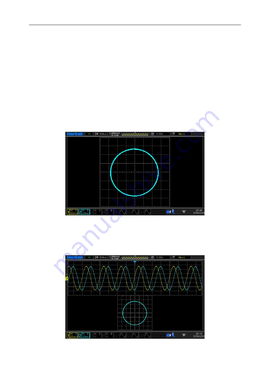
Test example: measure the phase difference between the input signals of the two
channels.
1. Connect a sinusoidal signal to CH1, and then connect a sinusoidal signal of the
same frequency, same amplitude and 90 ° phase difference to CH2.
2. Press the AutoScale key and adjust the vertical displacement of the CH1 and CH2
channels to 0 V.
3. After selecting the display mode as XY mode, turn the horizontal time base knob and
adjust the sampling rate appropriately to get better Lissajous graphics for better obser-
vation and measurement.
4. Adjust the vertical voltage scale of CH1 and CH2 to make the signal easy to observe.
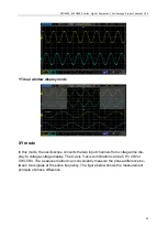
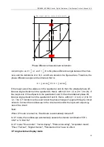
At this point, you should get the circle shown in the figure below.
5. Observe the measurement results in the figure above, and according to the phase
difference measurement principle diagram, you can get A / B (C / D) = 1, that is, the
phase difference angle between the two channel input signals is θ = ± arcsin1 = 90 °.
XY dual window display mode

