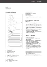
14
4
1
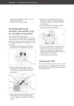
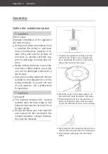
5. For exhaust air operation: Carefully in-
sert both plastic check valves into the air
outlet opening at the top of the appliance
(gently bend the flaps a little so as not to
break off the sensitive plastic tabs).
Attach the exhaust air hose 4 opening
with a diameter of 153 mm (see marking
on the hose) to the exhaust hood 1 and
secure it with a cable tie 14.
3
5
1
16
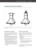
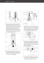
6. Place the two-piece flue screen 3 over
the mounting rails 5 above the exhaust
hood 1. The end with the ventilation slots
16 must be facing
upwards
.
8x
1
5
11 12
10
6
4
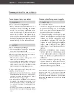
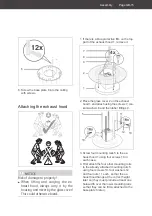
7. Lift the exhaust hood 1 with two persons
onto the housing, hold it to the base plate
6 at the top, and screw the mounting rails
5 to the base plate 6 using four screws
10, four washers 12 and four nuts 11.
14
4
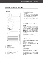
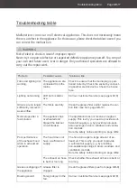
8. For exhaust air operation: Attach the ex-
haust air hose 4 opening with a diameter
of 150 mm (see marking on the hose) to
the vent opening in the ceiling and secure
it with a cable tie 14.
9. Connect the power supply.
4x
13
3
6
10. Pull the top of the flue screen 3 all the
way up to the ceiling and screw it to the
base plate 6 using four screws 13.
Assembly
Page GB-16

