18
TRACTOR ATTACHMENT
– Linkage Mounted Machines
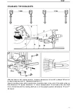
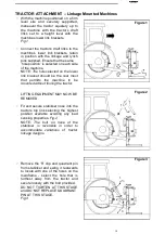
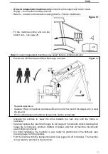
With the machine positioned on a firm
level site and securely supported,
maneuver the tractor squarely up to
the machine with the tractor’s draft
links set to a height level with the
machines lower link brackets.
Fig.1
Connect the tractor’s draft links to the
machine’s lower link brackets, retain
in position with the linkage and lynch
pins supplied. Ensure that the same
‘hole position’ is selected on each side
of the machine.
NOTE:
The hole selected on the lower
link bracket should be the rear most
that permits the machine to be
mounted without fouling the tractor.
LIFTING EQUIPMENT MAY NOW BE
REMOVED.
Fit and secure stabiliser nose into the
tractors top link selecting the highest
position available avoiding any load
sensing properties.
Fig.2
NOTE:
The bolt on nose of the
stabiliser is reversible in order to
accommodate variations of tractor
linkage designs.
Figure 1
Figure 2
1
2
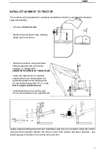
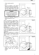
Remove the ‘R’ clip and quadrant pin
from stabiliser and swing it rearwards
to locate with one of the holes on the
mainframe
-
select the hole that is
furthest away from the tractor and
secure loosely with the bolt provided.
DO NOT TIGHTEN AT THIS STAGE
and DO NOT REPLACE QUADRANT
PIN AT THIS STAGE.
Fig.3
Figure 3
1
2
3
Содержание AM60
Страница 1: ...1 Operate Parts Manual Hedge cutter AM60 AM80 AM100...
Страница 6: ...6 SAFETY INFORMATION 4...
Страница 26: ...26 MACHINE CONTROLS Cable controlled machines only...
Страница 48: ...48...


