


2.
Description of the machine:
The rotary power harrow must be used for mechanical soil tillage and seed-bed preparation on
farms and in vineyards and orchards, as well as for row crops and specialty crops.
Moisture remains in the soil and the water balance of the soil is maintained since the soil is not
turned up as it is tilled. The vertically rotating cutters also prevent compaction of the soil, thus
resulting in optimum preparation of the seed-beds.
The power harrow is mounted on the tractor by means of a three-point suspension. It has five tine
units; the tine pick-up is rigidly mounted. The gear mechanism is driven via a PTO shaft and drives
the cutters in the housing via gear wheels.
The working depth is set by means of a hand spindle in combination with the support roller. The
friction clutch mounted on the PTO shaft protects both the harrow and the tractor from damage if
overloaded. An additional machine, such as a seeder, can be connected to the rotary harrow via a
further three-point suspension on the basic unit and a p.t.o. shaft on the main gear unit. In this way,
the seed-bed can be prepared and the seed sown in a single pass.
The working depth should be adjusted in line with the prevailing ground conditions in order to
obtain the best possible results. Large objects should be removed from the ground beforehand so
that the soil can be tilled correctly and to prevent premature wear on the tines.
The housing accommodates the various components making up the rotary power harrow. The
support roller, three-point frame, angular gear and tine units are bolted onto the housing.
The three-point frame is made of robust sheet metal and bolted onto the housing. The bolts of the
lower links support can be undone and the three-point frame displaced sideways on the rectangular
profile of the housing for off-center operation.
The angular gear which is mounted on the housing diverts the tractor’s rotary motion through 90°
and drives the tine units via gear wheels.
Each tine unit comprises a tine flange, guard plate, two tines, bearing housing, bearing and
connecting elements. The tines are mounted underneath the guard plate and serve to loosen the soil.
They are secured by means of special bushings, washers, bolts and lock nuts.
3
Содержание 1BQ1.3
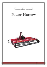
Страница 1: ...Instruction manual Power Harrow 1...
Страница 10: ...6 Technical data 7 Safety Decals 10...
Страница 11: ...11...
Страница 14: ...14...
Страница 16: ...16...


