background image

Section 4: Hinging the Flaps

15

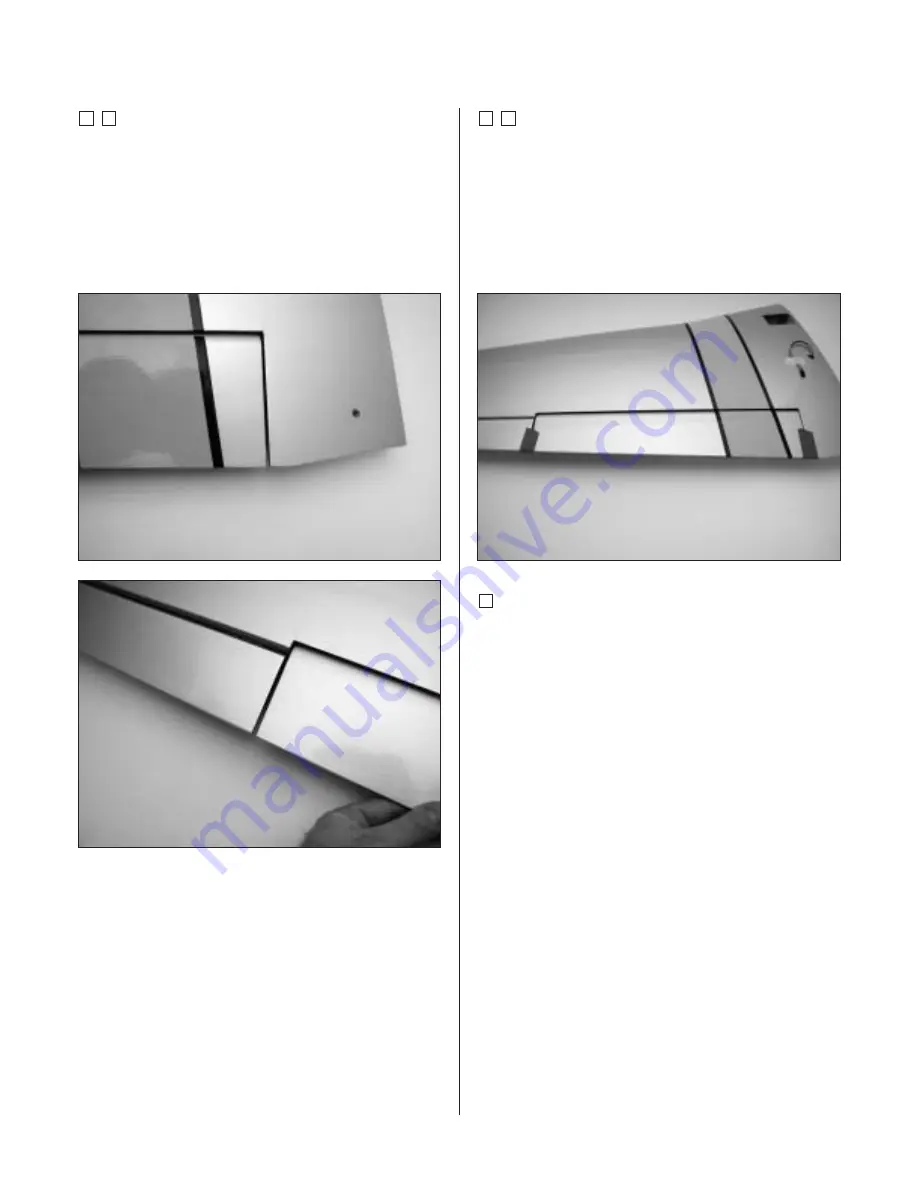
Step 4

Install the hinges in the flap and slide the flap into
position. Check to make sure the flap aligns with
both the aileron and wing trailing edge. If it does not,
enlarge the first 1/4" of the hinge holes in both the
wing and flap to provide more clearance for the center
of the hinge. This will allow the flap to be positioned
closer to the wing for alignment.

Step 5

Use 30-minute epoxy to install the hinges. Apply epoxy
to both the holes in the flap and wing using a toothpick.
Apply a light coat of epoxy to the hinge. Slide the flap
into position, and move it up and down to make sure the
hinges are aligned. Use tape around the division between
the flap and wing, as well as the flap and aileron, to hold
the flap until the epoxy fully cures.

Step 6

Repeat Steps 1 through 5 for the remaining flap.

Содержание P-51 Mustang 1.50 ARF

Страница 1: ...ater during WW II The Hangar 9 P 51 is a low wing high performance plane If this is your first attempt at flying this type of aircraft please consult a more experienced pilot to help in the setup and initial flights Specifications Wingspan 77 in 1956mm Length 68 in 1727mm Wing Area 1039 sq in 67 03sq dm Weight 13 14 lb 5 89 6 34 kg Engine 1 20 2 00 4 stroke Radio 6 channel w 10 servos ASSEMBLY MAN...

Страница 2: ...e Wing 28 Section 10 Mounting the Wing to the Fuselage 31 Section 11 Lower Air Intake Installation 32 Section 12 Stabilizer Installation 34 Section 13 Hinging the Elevators 36 Section 14 Hinging the Rudder 38 Section 15 Tail Wheel Installation 39 Section 16 Fuel Tank Assembly 41 Section 17A Engine Installation Saito 180GK 44 Section 17B Engine Installation Saito 200 TI 46 Section 18 Throttle Pushr...

Страница 3: ...valent 2 Low Profile Retract Servos JRPS703 Recommended JR Systems JR XF652 JR XP783 JR XP8103 PCM 10X Recommended Engines 1 50 2 18 2 cycle engines 1 20 2 00 4 cycle engines 4 Cycle Engine Saito 1 80 2 00 Small Parts 1 HAN2403 Aluminum Stabilizer Tube Set 2 HAN2409 Tail Wheel Assembly 3 HAN2410 Pushrod Set 4 HAN2412 Scale Detail Set Additional items sold separately HAN2408 Mechanical Retract Set ...

Страница 4: ... ruler tape measure T pins String Radio packing foam Petroleum jelly Adhesives Thin CA cyanoacrylate glue Thick CA cyanoacrylate glue CA remover debonder 6 minute epoxy 30 minute epoxy Pacer Z 42 Threadlock Canopy glue RC 56 Masking tape 3M blue recommended Propeller consult your engines instruction manual 24 Servo Lead Extension JRPA102 6 Servo Lead Extension JRPA094 An RC aircraft is not a toy I...

Страница 5: ...date of purchase This warranty does not cover any parts damage by use or modification In no case shall Horizon Hobby s liability exceed the original cost of the purchased kit Further Horizon Hobby reserves the right to change or modify this warranty without notice In that Horizon Hobby has no control over the final assembly or material used for the final assembly no liability shall be assumed nor ...

Страница 6: ...e leading edge of the aileron Step 3 Slide the aileron onto the wing until there is only a slight gap between the aileron and wing panel Remove the T pins and snug the aileron against the wing panel Slide the aileron towards the wing tip until there is only a 1 32 gap between the end of the aileron and wing tip Note Do not use CA accelerator during the hinging process The CA must be allowed to soa...

Страница 7: ...er towel to remove any excess CA accumulated on the wing or aileron surface Allow time for the CA to completely cure before moving to the next step Step 7 Firmly grasp the wing and aileron and gently pull on the aileron to ensure the hinges are secure and cannot be pulled apart Use caution when gripping the wing and aileron to avoid crushing the structure Step 8 Work the aileron up and down severa...

Страница 8: ...ailing edge of the wing and towards the wing tip as shown Note The aileron servo is mounted directly to the hatch Step 2 Install the recommended servo hardware grommets and eyelets supplied with the servo Temporarily install a long half servo arm JRPA212 onto the servo and position the servo onto the hatch so the servo arm is centered in the notch Also ensure the servo arm does not extend past the...

Страница 9: ... trim one of the servo mounting blocks to clear the servo wire Step 5 Remove the servo and use a 1 16 drill bit to predrill the holes for the servo mounting screws marked in the previous step Use the screws supplied with the servo to mount it to the servo mounting blocks Step 6 Connect a 24 Servo Lead extension JRPA212 to the servo lead Secure the connectors by tying them in a knot using dental fl...

Страница 10: ...m of slightly shaking the wing Step 9 Tie the string onto the servo extension Gently pull the extension through the wing using the string Untie the string when the servo lead has been pulled through Use tape to secure the servo lead to the wing to prevent it from falling back into the wing panel Step 10 Place the hatch cover in position in the aileron opening Measure in 1 8 on all four sides of th...

Страница 11: ...s using a 5 64 drill bit Use 2 3 drops of thin CA to harden the underlying wood This will prevent the screws from crushing the wood when they are tightened Secure the hatch using four 2 x 3 8 screws Step 12 Repeat Steps 1 through 11 for the remaining aileron servo Photo for Step 11 Photo for Step 11 ...

Страница 12: ...hread a clevis onto each end of the threaded rod The threaded rod should just be visible between the forks of the clevis Step 2 Attach the assembled control linkage to the aileron servo arm Step 3 Remove the back plate from the control horn using side cutters or a sharp hobby knife Use a 5 64 drill bit to drill out the mounting holes in the control horn Step 4 Position the control on the aileron b...

Страница 13: ...n remove it Place 2 3 drops of thin CA into the hole to harden the wood This will eliminate the potential of the screw pulling out of the wood Repeat this for each of the three holes Step 7 Attach the control horn using three 2 x 3 8 screws Step 8 Attach the aileron control linkage to the aileron control horn Note The linkage will be adjusted in Section 18 Radio Installation Step 9 Repeat Steps 1 ...

Страница 14: ...n mount in the flap The center of the mount is located 5 from the root of the flap wide end The plate is 1 1 4 wide and 1 deep Step 2 Locate three of the nylon flap hinges Apply a small amount of petroleum jelly to the hinge joint to prevent the epoxy from preventing movement of the hinge Step 3 Locate the holes in the wing and flap for the flap hinges Remove the covering if necessary from each ho...

Страница 15: ...inge This will allow the flap to be positioned closer to the wing for alignment Step 5 Use 30 minute epoxy to install the hinges Apply epoxy to both the holes in the flap and wing using a toothpick Apply a light coat of epoxy to the hinge Slide the flap into position and move it up and down to make sure the hinges are aligned Use tape around the division between the flap and wing as well as the fl...

Страница 16: ...ing dental floss Step 1 Locate the flap hatch The slot for the flap horn is positioned towards the trailing edge of the wing as well as towards the tip as shown in the photo Step 2 Install the recommended servo hardware grommets and eyelets supplied with the servo Temporarily install a long half servo arm JRPA212 onto the servo and position the servo onto the hatch so the servo arm is centered in ...

Страница 17: ...st not touch the hatch in order to isolate engine vibration Step 5 Remove the servo and use a 1 16 drill bit to predrill the holes for the servo mounting screws marked in the pervious step Use the screws supplied with the servo to mount it to the servo mounting blocks Step 6 Before installing the servo arm center the servo electronically using the transmitter Install the servo arm so it is positio...

Страница 18: ...ith a small weight such as a wheel collar attached as a device to pull the servo lead through the wing Lower the weight through the opening at the root of the wing as shown Step 9 Stand the wing on the tip and allow the weight to drop through the wing until it appears in the opening for the servo leads It may require a little help to pass by the wing ribs in the form of slightly shaking the wing S...

Страница 19: ...the servo hatch and the underlying hatch mounts Use caution not to accidentally drill through the top of the wing Step 12 Remove the servo hatch cover and re drill the holes using a 5 64 drill bit Use 2 3 drops of thin CA to harden the underlying wood This will prevent the screws from crushing the wood when they are tightened Secure the hatch using four 2 x 3 8 screws Step 13 Repeat Steps 1 throug...

Страница 20: ...eaded rod Thread a clevis onto each end of the threaded rod The threaded rod should just be visible between the forks of the clevis Step 2 Attach the assembled linkage to the flap servo arm Step 3 Remove the back plate from the control horn using side cutters or a sharp hobby knife Use a 5 64 drill bit to drill out the mounting holes in the control horn Step 4 Position the control horn on the flap...

Страница 21: ...hen remove it Place 2 3 drops of thin CA into the hole to harden the wood This will eliminate the potential of the screw pulling out of the wood Repeat this for each of the three holes Step 7 Attach the control horn using three 2 x 3 8 screws Step 8 Attach the flap control linkage to the flap control horn Note The linkage will be adjusted in Section 18 Radio Installation Step 9 Repeat Steps 1 thro...

Страница 22: ...2 x 3 8 screws that hold the retract in position Step 2 Prepare the retract linkage by threading a 4 40nut onto the shaft Slide a clevis keeper onto the metal clevis then thread the clevis onto the 4 40 x 10 1 2 threaded rod The threads of the threaded rod should be visible between the forks of the clevis Step 3 Connect the clevis to the retract actuator lever Slide the clevis keeper onto the clev...

Страница 23: ...ure the retract servo using the screws supplied with the servo Caution Drill only deep enough for the mounting screws If you drill too deep the bit will come out through the bottom of the wing Step 8 Using a ruler locate a hole in the servo arm that is 1 2 away from the center on the arm Drill the hole larger using a 7 64 drill bit Step 9 Locate an easy connecter and an easy connector back plate I...

Страница 24: ... be sure the retracts are working and locking correctly Section 8 Main Landing Gear and Wheel Doors Required Parts Wing assembly Landing gear door 2 Wheel collars 4 M3 x 8 screw 4 Axle mounts 2 Axles 2 6 32 set screw 2 8 32 set screw 2 4 x 7 16 screws 8 Main landing gear wheels 2 Landing gear door mounts 2 Required Tools Felt tipped pen Phillips screwdriver Drill Bit 1 8 Drill Moto tool w cut off ...

Страница 25: ...nto an 8 32 set screw Use the set screw to secure the axle Make sure to tighten the set screw onto the flat spot Step 4 Slide a wheel collar onto the axle Position the wheel collar against the axle mount and then secure its location using an M3 x 8 screw Step 5 Slide the wheel onto the axle Make sure the wheel can rotate freely on the axle Slide another wheel collar onto the axle and use an M3 x 8...

Страница 26: ...rect landing gear door tape it into position The correct door will fit the contour of the airfoil and have a small protrusion towards the leading edge of the wing Step 9 Draw two small marks on the landing gear door that will indicate the location of the landing gear strut Mark the landing gear where the lower edge of the landing gear door will be positioned Step 10 Remove the landing gear door an...

Страница 27: ...osition the landing gear door so the centerline and lower edge marks are aligned Mark the screw locations for the landing gear door mount screws Step 14 Drill the locations marked in the previous step using a 1 8 drill bit Step 15 Secure the landing gear door to the mounting brackets using four 4 x 7 16 screws Step 16 Move the landing gear to the retracted position Check the fit of the landing gea...

Страница 28: ... Repeat Steps 1 through 18 for the remaining retract Section 9 Joining the Wing Required Parts Wing assembly Wing joiner Wing dowels 2 Required Tools and Adhesives Ruler Masking Tape 5 minute epoxy 30 minute epoxy Rubbing alcohol Paper towels Step 1 Locate the two 1 4 x 2 wing dowels Draw a line 5 8 from one end on each dowel Step 2 Glue the dowel into the wing using 5 minute epoxy Apply epoxy to ...

Страница 29: ...e wing on a large flat surface with one panel resting flat on the surface The opposite wing tip should be 7 3 8 from the work surface Once satisfied with the fit separate the wing panels and remove the wing joiner Note Read through the remaining steps of this section before mixing any epoxy Hint It is extremely important to use plenty of epoxy when joining the wing panels It will also be helpful t...

Страница 30: ...anel Step 9 Apply epoxy to the exposed portion of the wing joiner Step 10 Apply epoxy to root wing rib of both panels Step 11 Carefully slide the wing panels together Apply enough pressure to firmly seat the two wing panels together causing any excess epoxy to ooze out from between the panels Use rubbing alcohol and a paper towel to remove the excess epoxy Check to make sure there are no visible g...

Страница 31: ...rand new blade to remove the covering 1 16 inside of the line drawn Use care not to cut into the underlying balsa as this will weaken the wing structure Step 3 Mix 1 2 ounce of 6 minute epoxy and coat both the wing and plywood plate Align the plate back onto the wing and clamp it in position Remove any excess epoxy using paper towels and rubbing alcohol Caution Use scrap plywood under the clamps t...

Страница 32: ...1 Use a felt tipped pen to trace around the heads of the wing bolts Step 2 Remove the wing bolts from the wing Locate the plywood tube locators and use medium CA to glue the locators in position Use the lines drawn around the bolt heads as a guide Step 3 Place a piece of wax paper between the fuselage and wing then bolt the wing onto the fuselage Step 4 Use medium grit sandpaper to lightly sand th...

Страница 33: ...g bolts in the wing Once the wing is removed slide the plastic guide tubes through the scoop and over the heads of the wing bolts The ends of the tubes will lock into the plywood tube locators when fully installed Step 7 Remove the wing bolts from the plane by sliding them out through the tubes Remove the tubes and roughen them using medium sandpaper Step 8 Apply a thin bead of thick CA around one...

Страница 34: ...cate both of the stabilizer tubes short and long Slide the tubes into one half of the stabilizer as follows short tube towards the leading edge and the long tube towards the trailing edge Required Parts Fuselage Stabilizer right and left Stabilizer tube short Stabilizer tube long 2 x 3 8 screw 2 Required Tools Drill Bit 3 32 Drill Phillips screwdriver ...

Страница 35: ... the remaining stabilizer half onto the tubes Step 4 Use a 3 32 drill bit to drill through the hole in the stabilizer into the stabilizer tube Be very careful to only drill through the tube not through the top of the stabilizer Step 5 Secure the tube in the one stab half using a 2 x 3 8 screw Step 6 Repeat Steps 4 and 5 for the remaining stab half ...

Страница 36: ... the elevator Step 3 Slide the elevator onto the stabilizer until there is only a slight gap between the stabilizer and elevator Remove the T pins and snug the elevator against the stabilizer Position the elevator so the tip aligns with the tip of the stabilizer Note Do not use CA accelerator during the hinging process The CA must be allowed to soak into the hinge to provide the best bond Using ac...

Страница 37: ... paper towel to remove any excess CA accumulated on the stabilizer or elevator surface Allow time for the CA to completely cure before moving to the next step Step 7 Firmly grasp the elevator and stabilizer and gently pull them apart to ensure the hinges are secure and cannot be pulled apart Use caution when gripping them to avoid crushing the structure Step 8 Work the elevator up and down several...

Страница 38: ...t a few steps Step 1 Locate three CA hinges and place a T pin in the center of each hinge Slide the hinges into the rudder Step 2 Slide the rudder onto the fin Align the top of the rudder with the top of the fin Remove the T pins and use thin CA to glue the hinges into position Apply CA to both sides of the hinges Step 3 Clean up any excess CA using CA remover debonder Once the CA has fully cured ...

Страница 39: ...File Side cutters Threadlocking compound Step 1 Locate the tail wheel Carefully drill the hole for the axle using a 20 drill Step 2 File a flat spot on the tail gear wire Position the flat off center slightly as shown in the photo Step 3 Install the 33 5 8 pushrod wire into the pushrod tube shown Make sure the threaded end is installed first leaving the non threaded end inside the radio area Hint ...

Страница 40: ...s to the steering arm in the outer hole as shown Slide the clevis keeper onto the clevis to keep the clevis from opening during flight Step 7 Position the steering arm in the center of the pre installed tail gear mount Make sure the set screw in the arm is facing forward Step 8 Slide the tail gear wire through the mount and steering arm Position the wire so there is 1 2 between the top of the moun...

Страница 41: ...r 2 x 3 8 screws Required Parts Clunk fuel pickup Metal caps 2 Fuel pickup tubing Fuel tank Rubber stopper M3 x 20 screw Metal tubes short and long Required Tools and Adhesives Hobby knife Phillips screwdriver Note The stopper provided with the P 51 has three holes that are not bored completely through the stopper The holes are for the fuel pickup fill and vent lines For these instructions only tw...

Страница 42: ...d on the side of the rubber stopper that makes the cap Loosely install the M3 x 20 screw through the center of the stopper Step 4 Bend the longer fuel tube carefully to a 45 degree angle using your fingers This will be the fuel tank vent tube Use care not to kink the tube while bending Step 5 Slide the vent tube into on of the remaining two holes in the stopper from the tank small cap side Step 6 ...

Страница 43: ...irections except for having the stopper facing down Note If you are planning on installing the Saito 200TI the fuel tank will be oriented differently Make sure the tank is built so the vent is pointing up with the fuel tank oriented as shown in the picture Step 8 Tighten the M3 x 20 screw carefully do not over tighten This allows the rubber stopper to form a seal by being slightly compressed thus ...

Страница 44: ...e The P 51 comes with the blind nuts preinstalled in the firewall They are located for the installation of the Saito 1 80 size four strokes If you plan on using another engine you may need to remove the blind nuts and drill new holes in the firewall for your particular engine Section 17B covers relocating the blind nuts for mounting the engine when using an engine mount different than supplied wit...

Страница 45: ...lywood engine mount spacers onto the bolts as shown Step 4 Install the engine mount Step 5 Install the spinner back plate and propeller Position the engine so there is between 1 16 and 1 8 gap between the back plate and fuselage Step 6 Remove the spinner back plate and tighten the screws holding the engine to the mount An 11 32 socket wrench will make this task a lot easier ...

Страница 46: ...ou are planning on using You may get lucky and not have to remove the blind nuts Step 2 If you must remove the blind nuts thread an 8 32 bolt partially into the nut Lightly tap the bolt to pop the blind nut away from the firewall This will prevent damaging the threads of the nuts Trim the cross brace to allow for the removal of the blind nuts near the top of the fuselage Step 3 Measure the distanc...

Страница 47: ...l centered here the two lines cross Step 5 Measure and record the distance between the holes in your particular mount Make sure your mount will be centered correctly when measuring Step 6 Transfer the measurements made in the last step to the firewall Remember to divide by two and measure from the centerline Note Another option is to determine the center vertically and horizontally of your mount P...

Страница 48: ...lind nuts removed in Step 2 Step 9 Install any accessories that may be required for your particular engine In the case of the Saito 200TI a needed valve must be attached to the mount Make any necessary adjustments to the fuselage to provide clearance if required Step 10 Install the engine of your choice at this time Use the method described in Step 5 of Section 17A to position the engine fore and ...

Страница 49: ... location for the throttle pushrod Mark the location with a felt tipped pen and drill the firewall for the pushrod tube using a drill and 1 8 drill bit Remove the engine if necessary Step 2 Test fit the throttle pushrod tube through the firewalland into the fuselage Once satisfied with the fit mix1 4 ounce of 6 minute epoxy and glue the pushrodinto the firewall Allow the epoxy to fully cure before...

Страница 50: ... of fuel tubing to the fuel tanks pickup and vent tubes Install the fuel tank into the fuselage from the radio compartment The stopper and fuel tubes will pass through the round hole in the firewall Use more foam to hold the tank in place and protect from vibration Hint Connect the red tube to the vent and the green tube to the pickup Important The Saito 200TI will require a new hole drilled in th...

Страница 51: ... the servo mounting screws Step 2 Remove the servos and drill the holes for the servo mounting screws using a 1 16 drill bit Note Place a drop of thin CA onto each screw hole to harden the wood around the hole Allow the CA to fully cure before installing the servos Step 3 Install the servos as shown The output shaft of the throttle servos faces rearward while the remaining servos will face forward...

Страница 52: ... foam to prevent damage that may be cause by engine vibration Step 7 Wrap the receiver battery in protective foam as you did the receiver Temporarily mount the receiver and battery into the fuselage It may be necessary to relocate the battery forward or aft to balance the model as described in the section Control Throws and Center of Gravity Step 8 Route the antenna out through the bottom of the f...

Страница 53: ... compound Step 1 Slide the rudder and elevator pushrod wires into the tube in the fuselage Make sure the threaded portion of the wires is on the outside of the plane near the tail group Step 2 Slide a clevis keeper onto a nylon clevis Thread the clevis onto the wire a minimum of 10 turns Repeat this step for both elevators linkages and the rudder linkage Step 3 Remove the back plate from a control...

Страница 54: ... be 5 16 deep don t drill through the top of the elevator Step 6 Install one of the 2 x 3 8 screws in a hole drilled then remove it Place 2 3 drops of thin CA into the hole to harden the wood This will eliminate the potential of the screw pulling out of the wood Repeat this for each of the three holes Step 7 Attach the control horn using three 2 x 3 8 screws Step 8 Center the elevator servo electr...

Страница 55: ...Install a servo arm onto the rudder servo Physically place the tail wheel in neutral Mark the pushrod where it crosses the holes in the servo arm Step 14 Bend the wire 90 degrees at the mark made in the previous step Step 15 Cut the wire 1 2 above the bend Step 16 Slide the wire through the inner hole in the rudder servo arm Secure the wire using a nylon wire keeper Step 9 Bend the wire 90 degrees...

Страница 56: ...lel in order to properly mount the rudder control horn Step 20 Thread three 2 nuts onto the threaded rods Slide the rod through the control horn then through the rudder Attach the back plate on the opposite side of the rudder as the control horn Finally thread three nuts onto the rods Tighten the nuts but don t crush the balsa Use threadlocking compound on the nuts to prevent them from loosening d...

Страница 57: ...connector onto the throttle pushrod Install the throttle servo arm in the neutral position as shown Step 3 Move the throttle stick and trim to low Check to make sure the carburetor will move to the low position when operating the servo Install an M3 x 8 screw to secure the easy connector to the throttle pushrod Check the movement of the throttle to verify there is no binding at either low or high ...

Страница 58: ...Parts Fuselage assembly Cowl Mounting screws 6 Required Tools and Adhesives Felt tipped pen Hobby knife Moto tool w cut off wheel and sanding drum Step 1 Mount the cowl using the 2 screws provided Make the appropriate cutouts in the cowl for the muffler exhaust and engine cooling Note If you are using the Saito 200TI it will be required to install a baffle inside the cowl to direct air over the re...

Страница 59: ...to the fuselage using Shoe Goo or similar type adhesive using the pictures on thebox as a guide Use tape to hold the parts until the adhesive cures Step 4 Glue the clear gun site into position using 6 minute epoxy Step 5 Glue the exhaust into position using Shoe Goo Step 6 Glue the guns into position using Shoe Goo ...

Страница 60: ...2 3 drops of dish soap added to the water and spray both the fuselage and sticky side of the decal This will allow you to reposition the decal if necessary Once satisfied with the position use a paper towel to squeegee out the water Allow the decal to dry overnight Note There may be some clouding under the decal but this will go away as the decal dries 60 Required Parts Fuselage assembly Canopy Re...

Страница 61: ...or the tail until the correct balance is achieved Stick on weights are available at your local hobby shop and work well for this purpose The following control throws offer a good place to start with your first flights We recommend only one rate setting for the P 51 As you become more familiar with the handling of your model you may wish to add a second rate setting Once the control throws for the ...

Страница 62: ...itromethane or hydrazine 7 I will not operate models with pyrotechnics any device that explodes burns or propels a projectile of any kind including but not limited to rockets explosive bombs dropped from models smoke bombs all explosive gases such as hydrogen filled balloons ground mounted devices launching a projectile The only exceptions permitted are rockets flown in accordance with the Nationa...

Страница 63: ...which is for flying with the other side for spectators 8 With the exception of events flown under AMA Competition rules after launch except for pilots or helpers being used no powered model may be flown closer than 25 feet to any person 9 Under no circumstances may a pilot or other person touch a powered model in flight Organized RC Racing Event 10 An RC racing event whether or not an AMA Rule Boo...

Страница 64: ... 5768 WE GET PEOPLE FLYING TM 2003 Horizon Hobby Inc 4105 Fieldstone Road Champaign Illinois 61822 217 355 9511 www horizonhobby com ...

Отзывы: