


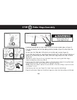


• Familiarize yourself with the Roller Hinge and Cam Lock terms detailed above in Figure 12.
• For ease of assembly, rest the Table Bed against the Crossbar (Figure 13) at the front of the
A-Frame.
• On one side of the Table Bed, lift the Cam Lock up all the way to unlock (Figure 14).
• In your other hand, hold one 3-Hole Roller Hinge at the Pivot Pin. With the Pivot Pin facing out
(away from the Table Bed), slide the bottom of the Roller Hinge between the Cam Lock and
th
e Bracket.
TIP:
Make sure that the Cam Lock is completely open when inserting the Roller Hinge,
otherwise assembly will be more difficult.
• Engage one of the holes in the Roller Hinge over the Bracket Pin. Figure 16 shows the Roller
Hinge installed correctly, with the Bracket Pin engaged in Setting C.
NOTE:
Refer to the Owner’s Manual for an explanation of the hole settings. If you are unsure,
use Setting C to start.
• Push down on the Cam Lock (Figure 15) to lock it and secure the Roller Hinge.
• Repeat on other side. Make sure the Roller Hinges are in the same hole setting on both sides.
STEP 4 Roller Hinge Assembly
C
B
A
1
12
FIGURE 13
FIGURE 14
FIGURE 15
FIGURE 16
Unlocked
Locked
Cam Lock
Pivot Pin
Bracket
FIGURE 12
NEVER disassemble the
Roller Hinge Pivot Pin.
WARNING
!
Bracket Pin
1


