background image

GB

81

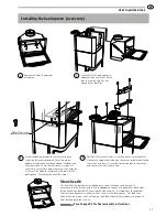
When installing the chimney, please refer to the chimney 
installation instructions. The chimney is connected to the stove 
as described below.

The insert comes from the factory ready for top connection. When 
connecting from the rear, the cover and connection must be swapped 
around. 

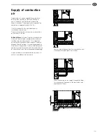
Top connection to the chimney

If connecting from the top, the whole stove surround must be installed 
before installation of the chimney can begin. 

The start pipe is placed over the connection on the insert. Make sure 
that the gasket on the connection is intact and in position. The stop 
washer is positioned over the collar on the start pipe. Install the 
remaining parts according to the instructions for the chimney.

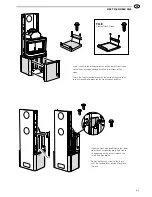
Chimney connection

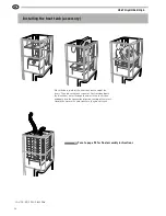
Important! If connecting from the top, the hot air 
grate must be installed before the chimney.

Chimney mantle

Stop washer

Start pipe

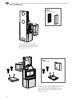
Rear connection to a masonry 

chimney

Mark out the centre for making a hole in the wall to the flue. 
Check that the connection height in the chimney breast is 
the same as the height of the connection pipe from the stove. 

Make a hole with a diameter of 
approx. 180 mm. 

Then cement the wall connector 
with fireproof mortar (not 
supplied with the product). 

Let the mortar dry before the 
stove is connected to the chimney. 

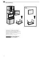
Move the stove back into place. 
Make sure that the connector 
gasket does not work loose from 
its position. If further sealing 
material is required, heat-
resistant sealant may be used.

Slide the connection pipe into 
the wall connector and seal the 
joint with sealing rope.

Use a hammer to tap out the 
knockout in the back plate. 
Hang the back plate into place 
on the side profiles as explained 
later in these instructions.

Содержание H26K Low

Страница 1: ...INSTRUCTIONS 26T 26K Installation...

Страница 2: ...n approved by a qualified inspector Your local chimney sweep must also be informed about the installation as this will affect the routines for regular chimney sweeping services 378 001 N ORDIC ECOLAB...

Страница 3: ...to welcome you to the Hand l family We hope your new stove will give you a great deal of pleasure Your choice of a Hand l stove is testimony to the high standards you demand in terms of quality and de...

Страница 4: ...ect the floor from any embers If the floor under the stove is combustible it must be protected with a minimum of 12 mm of non combustible material that covers at least 300 mm of the floor in front of...

Страница 5: ...o upward chimney connection B height from floor to c c rear chimney connection C distance from back to c c upward chimney connection D distance from back to rear chimney connection E distance from bac...

Страница 6: ...base plate 288 100 600 890 500 400 300 200 300 400 500 200 Combustible wall Permitted area for combustible material 435 120 8 9 0 810 Combustible wall Fire retardant wall of brick or concrete 365 50 7...

Страница 7: ...ustion is approximately 25 m3 hr The illustrations to the right show various installation alternatives The external diameter of the air duct connection on the stove is 64 mm In heated areas the duct m...

Страница 8: ...ible hose must be used See illustrations on pages 77 and 78 190 940 780 125 Eldstadsplan 3 2 0 Hearth plate for the Hand l 20 series optional BAV SE EX 0601 2 511299 Eldningsinstruktion och bruksanvis...

Страница 9: ...ng from the top the hot air grate must be installed before the chimney Chimney mantle Stop washer Start pipe Rear connection to a masonry chimney Mark out the centre for making a hole in the wall to t...

Страница 10: ...t the distance from the guide plate up to the rear edge of the door is 445 mm Check that the insert is vertically straight Position the guide plate according to the installation dimensions and ensure...

Страница 11: ...one at this stage Use the upper outlet on a tall model only if installing a baking oven Otherwise use the lower outlet Assemble the rear side profiles with two screws M6x20 each Check that the profile...

Страница 12: ...rows are even and straight so that the tiles do not become misaligned or the gaps between them too large While you are installing the stove make sure that all the stones tiles are level and that each...

Страница 13: ...front side profile onto the lower side stone s suspension plate and secure its upper edge with screws in both the insert and side profile Do not tighten the screw in the insert until the second layer...

Страница 14: ...side profile Check that it is at the same height as the side stones and then tighten the screws Screw the upper front profiles securely into place in the side stones Press the profile upwards so that...

Страница 15: ...amper can be opened and closed properly Position the top stones on top of the stove Pins are placed in the soapstone top for the grate to rest on Position the adjusting screws on the top of the back p...

Страница 16: ...straight Push in the lower side stones from the front so that their suspension plates hook into the horizontal keyholes of the side profiles Make sure that there is a 5 mm gap between the stone and t...

Страница 17: ...th the insert and side profile Do not tighten the screw in the insert until the second layer of side stones are in place Install the two lower front profiles on the lower front stone so that they are...

Страница 18: ...mm between the screw flange and the stone Then insert them into the smaller keyholes in the side profiles and check that they are level before finally tightening the screws Hang the middle side stone...

Страница 19: ...es securely into place in the side stones Press the profile upwards so that its bent edge is against the lower edge of the side stone Slide the end of the flexible aluminium hoses down into the convec...

Страница 20: ...o the upper front stone leaving 4 5 mm between the screw flange and the soapstone Hang the stone into place in the keyholes and allow it to rest against the bent edge of the side profile Check that it...

Страница 21: ...n the pins or the cast edge of the tile top Check that the damper can be opened and closed properly Position adjusting screws on the top of the back plate and screw them down so that the screw heads a...

Страница 22: ...nd secure it onto the back or top of the oven depending on whether the chimney is to be connected from the rear or directly upwards Hang the stone into place in the keyholes and allow it to rest again...

Страница 23: ...ng onto the surface Adjusting screw Position the screen so that it is resting on the corner profiles Slacken the uppermost screws on the corner profiles and fasten the screen into these Screw the conv...

Страница 24: ...IAV SE EX 1019 3 811008 Place the base plate of the heat tank on the top of the insert Then place the tank stones as illustrated and push the aluminium hoses through the holes in the tank stone and do...

Страница 25: ...den www handol se NIBE Stoves reserves the right to change colours materials dimensions and models at any time without special notice Your dealer can provide you with the latest information The stoves...

Отзывы: