Technical Manual
VERSION 2.0 -10-18-2018
71
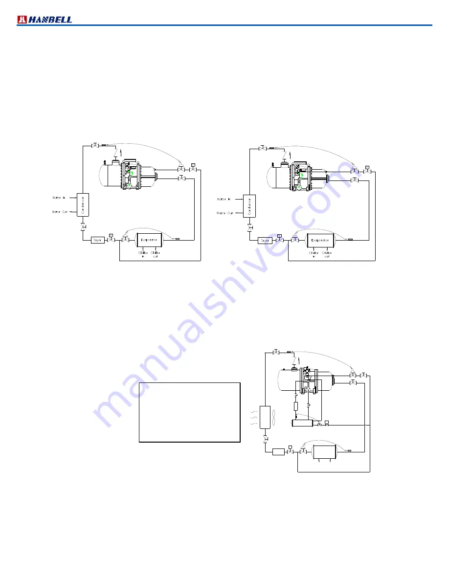
Liquid injection applied with high temperature expansion valve
Select
the high temperature expansion valve, which can sense the discharge temperature with its remote bulb. This
can control the opening of expansion valve proportionally, and can reach the best cooling effect; it will control the
compressor discharge temperature at an optimal situation of around 80
°
C.
It can also be installed with an additional solenoid valve or service valve in front of the high temperature expansion
valve for the maintenance purposes. The solenoid valve will be opened while starting the compressor. The
equilibrium tube of high temperature expansion valve should be connected to the highpressure side to counter the
internal pressure.
However, when additional cooling in compression chamber like economizer operation, oil cooler application is used,
or when condensing temperature is low, discharge temperature may be kept low and liquid injection may not be
turned on, although motor load is severe and motor coil temperature is high. This may lead to motor failure.
Therefore, in applications mentioned above, Pt100 or Pt1000 for liquid injection to motor is recommended instead.
Figure 61 Liquid injection (high temperature type) Figure 62 Liquid injection (high temperature type)
connected to motor to compression chamber
b. Oil cooler applications
Compared to liquid injection applications, external oil cooler applications reduces the discharge temperature and at the
same time gives better efficiency. Oil cooler application can be classified into 3 types: cooling by refrigerant, cooling by
ambient air, cooling by cooling water. Oil cooler capacity can be calculated manually or using HANBELL selection
software. When calculating
manually, worst case operating conditions must be considered: minimum evaporating
temperature, maximum suction gas superheat, maximum condensing temperature and the operation mode.
Cooling by refrigerant
The cooler uses refrigerant as the cooling medium. A basic
refrigerantcooled oil cooling system is shown in Figure 63.
Figure 63 Oil cooling by refrigerant
Aircooled oil cooling (cooling by ambient air)
Содержание RC2 Series
Страница 24: ...Technical Manual VERSION 2 0 10 18 2018 24 UNIT SI mm Imperial in UNIT SI mm Imperial in ...
Страница 25: ...Technical Manual VERSION 2 0 10 18 2018 25 SI mm Imperial in UNIT UNIT SI mm Imperial in ...
Страница 26: ...Technical Manual VERSION 2 0 10 18 2018 26 SI mm Imperial in UNIT UNIT SI mm Imperial in ...
Страница 27: ...Technical Manual VERSION 2 0 10 18 2018 27 UNIT SI mm Imperial in ...
Страница 28: ...Technical Manual VERSION 2 0 10 18 2018 28 ...
Страница 29: ...Technical Manual VERSION 2 0 10 18 2018 29 UNIT SI mm Imperial in ...
Страница 30: ...Technical Manual VERSION 2 0 10 18 2018 30 ...
Страница 31: ...Technical Manual VERSION 2 0 10 18 2018 31 ...
Страница 32: ...Technical Manual VERSION 2 0 10 18 2018 32 ...
Страница 33: ...Technical Manual VERSION 2 0 10 18 2018 33 ...
Страница 34: ...Technical Manual VERSION 2 0 10 18 2018 34 UNIT SI mm Imperial in ...
Страница 35: ...Technical Manual VERSION 2 0 10 18 2018 35 2 RC2 B outline drawings ...
Страница 36: ...Technical Manual VERSION 2 0 10 18 2018 36 ...
Страница 37: ...Technical Manual VERSION 2 0 10 18 2018 37 ...
Страница 38: ...Technical Manual VERSION 2 0 10 18 2018 38 ...
Страница 39: ...Technical Manual VERSION 2 0 10 18 2018 39 ...
Страница 40: ...Technical Manual VERSION 2 0 10 18 2018 40 ...
Страница 41: ...Technical Manual VERSION 2 0 10 18 2018 41 ...
Страница 42: ...Technical Manual VERSION 2 0 10 18 2018 42 ...
Страница 43: ...Technical Manual VERSION 2 0 10 18 2018 43 ...
Страница 44: ...Technical Manual VERSION 2 0 10 18 2018 44 SI mm Imperial in UNIT ...
Страница 60: ...Technical Manual VERSION 2 0 10 18 2018 60 ...
Страница 83: ...Technical Manual VERSION 2 0 10 18 2018 83 NOTES ...


