background image


55 


7. Applications 
7.1 Additional cooling 
 
When  compressors  operate  at  following  application  conditions,  installation  of  an  additional  cooling  apparatus  is 
recommended  to  control  discharge  temperature,  maintain  proper  temperature  of  lubricant  and  ensure  safety  of  the 
motor. 
 

  Air-cooled system 

  High compression ratio system such as heat pump, low temperature and refrigeration systems 

  High discharge temperature system such as heat recovery system 

  Any other heavy duty application 

 
There are two type of additional cooling methods: 
 
a.  Liquid injection applications 

In areas with high condensing temperature and/or low evaporating temperature as in the limitation diagram, additional 
cooling  is  required  in  order  for  the  compressor  to  work  properly.  A  relatively  simple  method  of  additional  cooling  is 
direct refrigerant injection  into  the compressor, to motor or compression chamber or to both places  at the same time 
once needed. 

The  purpose  of  liquid  injection  systems  is  to  prevent  the  compressor  from  overheated.  The  system  is  with  a  liquid 
injection  expansion  valve  between  the  liquid  line  and  compressor  for  cooling  down  the  compression  chamber  and 
motor  to  ensure  the  continuous  and  safe  running  of  the  compressor.  The  suction  superheat  should  be  controlled 
between 5K~10K for air-cooled and heat  pump chillers by means  of expansion  valve devices. These devices can  be 
adjusted by the stem of the expansion valve to control suction superheat by means of refrigerant flow rate. During the 
initial  startup,  the  loading  of  the  chiller  is  heavy  due  to  high  temperature  chilled  water,  so  the  liquid  injection  devices 
capacity should be selected or calculated enough to reduce the overheat of the compressor. 

Calculating the cooling capacity of liquid injection devices: 
Liquid injection devices can be calculated with the HANBELL selection software or manually. For manual calculation, 
consider the most extreme conditions to be expected during actual operations i.e. minimum evaporating temperature, 
maximum suction gas super heat and condensing temperature. 

Liquid injection applied with low temperature expansion valve: 
When the compressor applied in the low temperature system (E.T. 

 -10°C) the compression ratio is high at this 

condition, also the discharge temperature will be very high. The design of the liquid injection system for low 
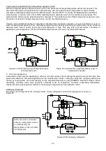
temperature application is similar to the illustration shown in figure below. There are two connectors for the liquid 
injection in the compressor, one is in the motor side to cool down the motor temperature and reduce the discharge 
temperature. The other is in the compression chamber side and its function is to reduce the discharge temperature and 
increase the compression efficiency. However, when additional cooling in compression chamber like economizer 
operation, oil cooler application is used or when condensing temperature is low, discharge temperature be kept low 
and liquid injection may not be turned on, although motor load is severe and motor coil temperature is high. This may 
lead to motor failure. Therefore, in application mentioned above Pt100 or Pt1000 for liquid injection to motor is 
recommended instead. 


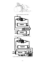
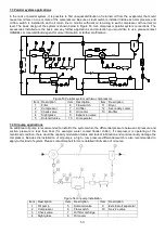
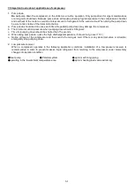
Figure 41 Liquid injection connected to motor 

Figure 42 Liquid injection connected to compression chamber 

Содержание RC2-AV Series

Страница 1: ...ge 11 4 Compressor lifting and installation 12 4 1 Compressor lifting 12 4 2 Mounting the compressor 12 4 3 RC2 AV series compressor outline drawings 14 4 4 Compressors accessories 37 5 Electrical dat...

Страница 2: ...rolled under severe quality procedures and good service to all customers RC2 AV series compressor is equipped with liquid injection economizer connection PTC motor temperature thermistors discharge te...

Страница 3: ...s and description of design 2 1 Compressor nomenclature RC 2 x x x x A V V for applications with variable frequency driver Refrigerant Code A R134a R1234ze Compressor Displacement at 50Hz m 3 hr RC mo...

Страница 4: ...6 1750 3550 84 70 16 610 RC2 410AV 407 1750 4750 125 78 16 730 RC2 430AV 423 1750 4750 125 78 16 735 RC2 470AV 471 1750 4750 144 90 18 800 RC2 510AV 508 1750 3550 117 98 20 760 RC2 550AV 549 1750 4750...

Страница 5: ...able box RC2 200AV RC2 230AV RC2 260AV RC2 300AV RC2 310AV RC2 340AV RC2 370AV RC2 410AV RC2 430AV RC2 470AV RC2 510AV RC2 580AV construction 1 2 3 4 5 6 7 8 9 14 15 16 17 18 19 20 21 22 23 24 25 26 2...

Страница 6: ...8 Oil separator baffle 16 Vi plug key 24 Oil guiding ring RC2 710AV RC2 790AV RC2 830AV RC2 930AV Construction Figure 4 Item Description Item Description Item Description Item Description 1 Compresso...

Страница 7: ...discharge ends as well as angular contact ball bearings i e axial bearings at discharge end A three phase two pole squirrel cage induction motor drives the compressor The motor rotor is located on the...

Страница 8: ...as is trapped inside the interlobe space b Compression As the male rotor and female rotor meshes the interlobe space moves towards to discharge end and its volume decreases so that gas pressure increa...

Страница 9: ...ing for signals connected to VFD should be isolated from wirings of VFD power supply at a distance 3 PLC microcontroller and VFD should be well grounded respectively to prevent cross interference Proc...

Страница 10: ...will rise simultaneously In order to keep compressor running safely and continuously Hanbell recommends the following additional cooling devices 1 Oil cooler or 2 Liquid injection to chamber or 3 Liq...

Страница 11: ...icant flow to bearings While reverse running it is unable to see the oil flow via sight glass The normal oil level in the compressor oil sump should be maintained above the top of the low level sight...

Страница 12: ...d then change oil every 20 000 hours or after 3 years continuous running while the system operates in good condition 2 Avoid clogging in oil filter with debris or swarf which may cause bearing failure...

Страница 13: ...ins or steel cables Figure 9 Lifting the compressor with safety ropes 4 2 Mounting the compressor The installation of the compressor in the refrigeration system should be made accessible and make sure...

Страница 14: ...ischarge piping to minimize vibration and noise 3 Remove oxidized impurities swarf or debris brought by welding in the piping tubes If they fall into the compressor the oil filter might be clogged res...

Страница 15: ...4 3 RC2 AV series compressor outline drawings...

Страница 16: ...15...

Страница 17: ...16 UNIT SI mm Imperial in...

Страница 18: ...17...

Страница 19: ...18...

Страница 20: ...19...

Страница 21: ...20...

Страница 22: ...21...

Страница 23: ...22...

Страница 24: ...23...

Страница 25: ...24...

Страница 26: ...25...

Страница 27: ...26...

Страница 28: ...27...

Страница 29: ...28...

Страница 30: ...29...

Страница 31: ...30...

Страница 32: ...31...

Страница 33: ...32...

Страница 34: ...33 SI mm Imperial in UNIT...

Страница 35: ...34...

Страница 36: ...35...

Страница 37: ...36...

Страница 38: ...evel switch Oil drain valve Liquid injection system solenoid valve expansion valve Liquid injection system solenoid valve stop valve Horizontal check valve External oil separator External oil filter O...

Страница 39: ...D E F G H I 2 102 6 53 69 91 65 90 85 5 2 1 2 122 6 69 89 111 85 110 97 5 3 138 6 80 99 121 95 120 108 5 4 163 6 96 124 146 120 145 123 5 Figure 12 Suction check valve outline drawing Horizontal type...

Страница 40: ...97 6 3 138 4 95 99 121 80 100 120 108 6 4 163 4 120 124 146 96 125 145 123 6 6 238 5 190 195 216 146 190 215 160 6 No 1 2 3 4 5 6 7 8 Item Body C clipper Spring Valve platet Gasket Nut Guide seat Shaf...

Страница 41: ...2 90 Suction Copper 3 1 8 76 145 50 79 8 90 3 5 8 92 4 103 4 1 8 105 1 116 Steel 3 90 2 105 3 1 2 102 8 117 4 115 6 128 RC2 510 RC2 550 RC2 580 Discharge Copper 2 1 8 66 120 45 54 3 65 2 5 8 67 77 3 1...

Страница 42: ...75 256 115 18 105 M16x2 105 2 70 90 60 69 91 6 5 122 86 280 128 18 120 M16x2 120 2 1 2 90 110 67 89 111 6 5 137 95 307 153 18 140 M16x2 140 3 100 120 80 99 121 6 5 154 117 398 177 22 160 M20x2 5 160 4...

Страница 43: ...frequency drive application Technical data of INT69HBY Supply voltage AC 50 60 Hz 115 120V 15 10 3VA AC 50 60 Hz 230 240V 15 10 3VA Ambient temperature 30 70 Relay output max AC 240V max 2 5A C300 mi...

Страница 44: ...DC Max voltage 300V DC AC Max current 0 5A DC AC Figure 21 Oil level switch Notes 1 There is a triangle mark on the float indicating the sensor direction Before you install an oil level switch on a co...

Страница 45: ...trol power lines refer to the drawing below cable box RC2 200 620AV cable box RC2 1020 1530AV cable box Figure 25 IP54 cable box Liquid injection system solenoid valve expansion valve additional cooli...

Страница 46: ...ature and parallel systems system with long piping Hanbell specially designs a complete series of external oil separators OS series with characteristics of high separation efficiency and low pressure...

Страница 47: ...caused by resonance Drawing Vertical OS40 65 Horizontal OS80 150 Figure 28 OS series external oil separator m External oil filter External oil filter is an optional accessory It is suggested to instal...

Страница 48: ...or oil return port 47 Qmax Recom l min switch value l min selectable range for fixed switch mm 20 0 4 12 40 0 6 25 60 1 5 40 Figure 30 Oil flow switch Average pressure loss 0 4 bar at Qmax Hysteresis...

Страница 49: ...Pt1000 sensor on motor coil as optional accessories This temperature sensor along with controller of the system monitor motor coil temperature and then control on off of liquid injection valve accordi...

Страница 50: ...Insulation test voltage U is AC 1 5kV Compressors motor can be equipped with either Pt100 or Pt1000 sensor to precisely control liquid injection and maintain motor coil while running Please specify Pt...

Страница 51: ...ngly recommended especially when the wiring length between VFD and motor exceeds 5m otherwise it might cause serious damage to the inverter or the motor Please discuss with your VFD providers whether...

Страница 52: ...ck response while the temperature approaches to their set point thermistors must be connected in series to a controller INT69HBY in cable box as a guardian to protect compressor Alarm lamp for this pr...

Страница 53: ...Those functions as speed control malfunction feedback VFD reset should be workable 2 Should follow the nameplate of compressor 3 Acceleration 50 60 sec from 0Hz to 50Hz deceleration vice versa 6 Comp...

Страница 54: ...s that might happen at jobsites This table could be a guide for engineers when problems are found PROBLEMS POSSIBLE CAUSES REMEDY CORRECTIVE ACTION Sudden trip of motor thermistor sensor Low refrigera...

Страница 55: ...er Check and clean the condenser Refrigerant overcharge Reduce the refrigerant charge Air moisture in refrigerant system Recover purify refrigerant and vacuum system Improper expansion valve Check and...

Страница 56: ...ler is heavy due to high temperature chilled water so the liquid injection devices capacity should be selected or calculated enough to reduce the overheat of the compressor Calculating the cooling cap...

Страница 57: ...d motor coil temperature is high This may lead to motor failure Therefore in applications mentioned above Pt100 or Pt1000 for liquid injection to motor is recommended instead Figure 43 Liquid injectio...

Страница 58: ...ooler to reject heat from the cooling medium The basic water cooled oil cooling system is shown in Figure 47 Figure 47 Oil cooling by water Note 1 Please decide appropriate oil cooler capacity by refe...

Страница 59: ...dditional middle connection is at a similar level to the intermediate pressure with a two stage system As a result of these features a screw compressor of this design can be combined with an additiona...

Страница 60: ...59 Figure 50 Installation of ECO muffler Figure 51 System with economizer sub cooler Figure 52 System with economizer flash type sub cooler...

Страница 61: ...on 1 Filter 6 Flow switch 11 Dryer 2 Compressor 7 Oil filter 12 Secondary cooler 3 Check valve 8 Oil cooler 13 Muffler 4 Sight glass 9 Expansion valve 5 Solenoid valve 10 Oil separator 7 4 Oil pump ap...

Страница 62: ...uction pressure when pumping down should is 0 5kg cm2 c Time for pumping down should be shorter than 15 seconds d When doing pump down notice the high discharge temperature It should not go over 110 e...

Отзывы: