


51
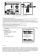
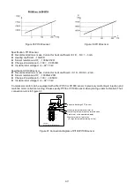
If FB is 3Hz, VC would be 400
÷
80
×
3 = 15 (V)
3. For safety reason, the recommended way to check V/F setting is to operate VFD without connecting motor. If the
ratio of output voltage and frequency is always equal to VMAX / FMAX, V/F setting could be finished.
4. Once VFD starts to drive motor, please check the output current at the beginning. Incorrect V/F setting would result
in an excessive current. If so, please shutdown VFD immediately and recheck all of the settings.
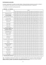
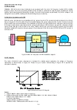
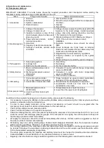
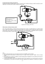
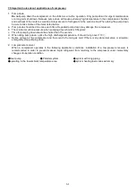
5.4 Compressor protection devices
The table below shows the list of protection devices which protects the compressor to operate safely. Apply protection
devices listed below to ensure your compressor could run under normal condition.
Protection device
Set point
Remark
Motor wiring temperature protector (PTC sensor) Cutout 110
℃
, cut in 100
℃
※
Standard
Discharge temperature protector (PTC sensor)
Cutout 110
℃
, cut in 100
℃
※
Standard
Oil level switch
Optional
Oil filter pressure differential switch
Cutout 1.5kg/cm
2
g
Optional
Oil flow switch
Optional
Pt100 or Pt1000 for liquid injection to motor
chamber.
Depends on applications. Normally the injection starts at 60
℃
and cut out at
50
℃
Optional
※
Manual reset suggested
Motor thermistors and discharge thermistors are temperature sensors with quick response while the temperature
approaches to their set point; thermistors must be connected in series to a controller (INT69HBY) in cable box as a
guardian to protect compressor. Alarm lamp for this protector is required to be embedded on control panel as indicator.
Any intention to short controllers for starting of compressors is prohibited. It is beyond Hanbell warranty of compressors
if any action mentioned is found.
Note: when any protection device trips, please do troubleshooting and reset manually. Do not let the compressor reset
automatically after any trip!
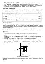
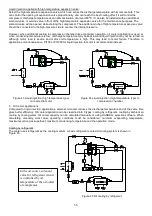
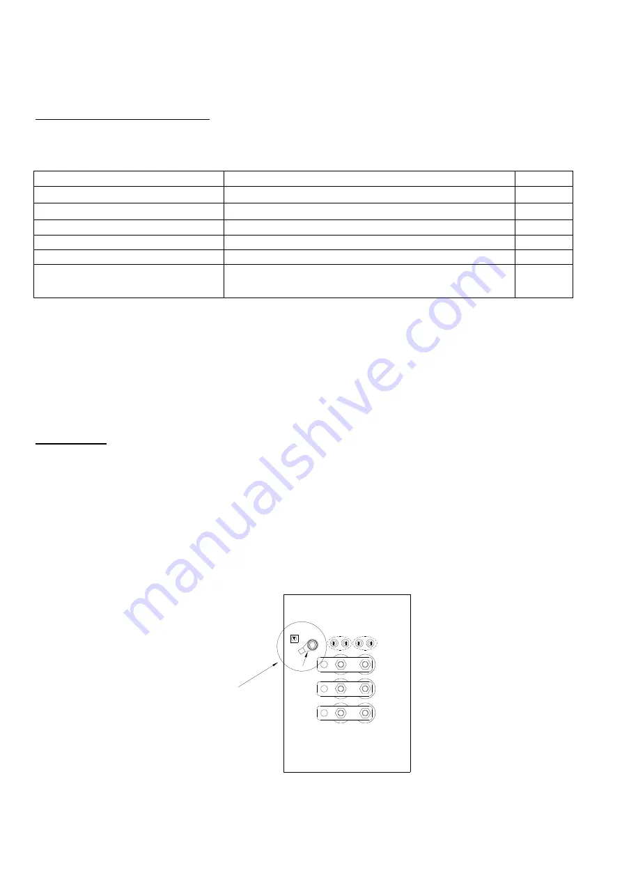
5.5 Grounding
There’s a grounding terminal on terminal plate. Please connect it to grounding of system control panel.
Suggestion:
a.
The regular setting of electric leak protection should be greater than 50mA; for humid locations, 25mA is
recommended.
b.
Grounding voltage of casing should be less than 50V; for humid locations, the maximum is 25V.
c.
Grounding resistance should be less than 500 Ohm.
d.
Air cut board (ACB) is regularly equipped with electric leak protection. Please refer to related settings for its
normal action.
e.
If electric leak protection is active, please check if insulation of equipments is normal and if its wiring and setting
are correct.
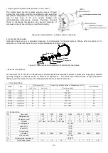
Grounding
B:Pt100
Ω
/ Pt1000
Ω
(Optional)
A:PTC
terminal
Earth Bolt
A
B
U
V
W
Figure 40 Grounding Terminal
Please make sure nothing is wrong before turning on power. If there are any questions, please contact the supplier of
equipments.
Содержание RC2-AV Series
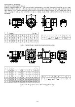
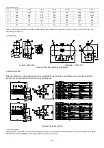
Страница 15: ...4 3 RC2 AV series compressor outline drawings...
Страница 16: ...15...
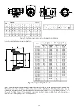
Страница 17: ...16 UNIT SI mm Imperial in...
Страница 18: ...17...
Страница 19: ...18...
Страница 20: ...19...
Страница 21: ...20...
Страница 22: ...21...
Страница 23: ...22...
Страница 24: ...23...
Страница 25: ...24...
Страница 26: ...25...
Страница 27: ...26...
Страница 28: ...27...
Страница 29: ...28...
Страница 30: ...29...
Страница 31: ...30...
Страница 32: ...31...
Страница 33: ...32...
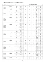
Страница 34: ...33 SI mm Imperial in UNIT...
Страница 35: ...34...
Страница 36: ...35...
Страница 37: ...36...


