background image

12

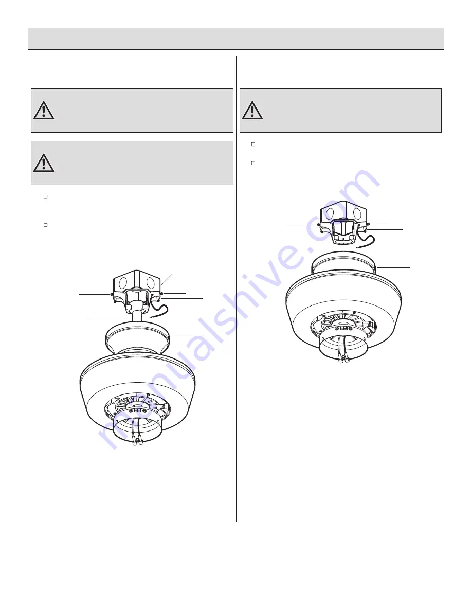
Assembly — Hanging the Fan (optional)

Standard ceiling mounting

7a

Close-to-ceiling mounting

7b

WARNING:


Make sure the tab on the mounting bracket (A)

properly sits in the groove in the hanger ball (D) before attaching 
the canopy (B) to the mounting bracket (A) by turning the canopy 
(B) until it drops into place.

WARNING:


The locking slots of the canopy (B) are provided 

only as an aid to mounting. Do not leave the fan assembly 
unattended until all four canopy mounting screws with lock 
washers (GG) are engaged and firmly tightened.

WARNING:


The locking slots of the canopy (B) are provided

only as an aid to mounting. Do not leave the fan assembly
unattended until all four canopy mounting screws with lock
washers (GG) are engaged and firmly tightened.

GG

A

GG

GG

A

GG

D

Slide the canopy (B) up to the ceiling. Make sure you have 
placed the wires safely into the outlet box.

Secure the canopy (B) to the mounting bracket (A) with the 
four canopy mounting screws with lock washers (GG) included 
with your fan.

Remove the fan from the hook on the mounting bracket (A).

Secure the canopy (B) to the mounting bracket (A) with the 
four canopy mounting screws with lock washers (GG) provided.

Outlet Box

B

B

Содержание JANEEN AK452-CB

Страница 1: ...for your home improvement needs Thank you for choosing Hampton Bay 1 855 HD HAMPTON HAMPTONBAY COM Questions problems missing parts Before returning to the store 8 a m 7 p m EST Monday Friday 9 a m 6...

Страница 2: ...s spliced conductors should be turned upward and pushed carefully up into the outlet box The wires should be spread apart with the grounded conductor and the equipment grounding conductor on one side...

Страница 3: ...stallation or by affixing any accessories is not covered by this warranty Because of varying climatic conditions this warranty does not cover any changes in brass finish including rusting pitting corr...

Страница 4: ...AA BB CC DD EE FF Plastic wire nut Blade attachment screw and fiber washer 7 5 Watt LED bulb 1 5V AAA battery Extension cord Plastic plug Part Description 3 16 2 2 1 1 Quantity HARDWARE INCLUDED Pre...

Страница 5: ...Blade arm Light kit Receiver Remote control Quantity 5 5 1 1 1 Part A B C D E Quantity 1 1 1 1 1 Description Mounting bracket preassembled Canopy Canopy bottom cover preassembled Hanger ball downrod...

Страница 6: ...ion hanger bar not included as shown above Outlet Box Outlet Box Hanger Bar Outlet Box Recessed Outlet Box A WARNING To reduce the risk of fire electric shock or personal injury mount the fan to an ou...

Страница 7: ...ottom of the hanger ball downrod assembly D with the holes in the collar on top of the fan motor assembly E Carefully insert the clevis pin II through the holes in the collar and the hanger ball downr...

Страница 8: ...motor assembly E collar Remove three of the six collar mounting screws with lock washers LL every other one from the collar on top of the fan motor assembly E LL KK WARNING Failure to completely tigh...

Страница 9: ...t A is toward the outlet box Securely tighten the two mounting screws 5b 5a Hanging instructions for standard mounting Hanging instructions for close to ceiling mounting WARNING The tab in the ring mu...

Страница 10: ...e located inside the battery compartment I J DD Setting the Code on the Remote Setting the Code on the Receiver Slide the code switches on the receiver I to the same positions as set on the remote con...

Страница 11: ...Pin Connector Make wire connections from the receiver I and fan to the outlet box as follows using the wire nuts AA From Receiver To Outlet Box Black wire AC in L Black wire Hot White wire AC in N Whi...

Страница 12: ...GG are engaged and firmly tightened WARNING The locking slots of the canopy B are provided only as an aid to mounting Do not leave the fan assembly unattended until all four canopy mounting screws wi...

Страница 13: ...her BB into the blade arm G but do not tighten Repeat for the two remaining screws and fiber washers BB Tighten each screw securely starting with the center screw Make sure the blade F is straight Rep...

Страница 14: ...provided Be sure to tighten all screws 14 Assembly Installing the Light Kit Attaching the light kit to the switch housing 11 Installing the light bulbs 12 E OO H PP Install two 7 5 watt LED bulbs CC i...

Страница 15: ...ousing cover QQ Install the switch housing cover QQ to the switch housing with light kit mounting screws OO provided Assembly Installing the Light Kit continued Installing the fan without the light ki...

Страница 16: ...e 3 times turns the fan on low speed Press and release 4 times turns the fan off Press and release the button to turn the light on or off Press and hold the button to activate the dimmer function Pres...

Страница 17: ...rsing the direction of the blade rotation Warm weather Counterclockwise Direction A downward air flow creates a cooling effect This allows you to set your air conditioner on a warmer setting without a...

Страница 18: ...e motor hub are tight Make sure the wire nut connections are not rattling against each other or the interior wall of the switch housing Allow a 24 hour breaking in period Most noises associated with a...

Страница 19: ...pursuant to Part 15 of the FCC Rules These limits are designed to provide reasonable protection against harmful interference in a residential installation This equipment generates uses and can radiate...

Отзывы: